background image

46

Copying MultiValve Presets, Titles and Controller Assignments

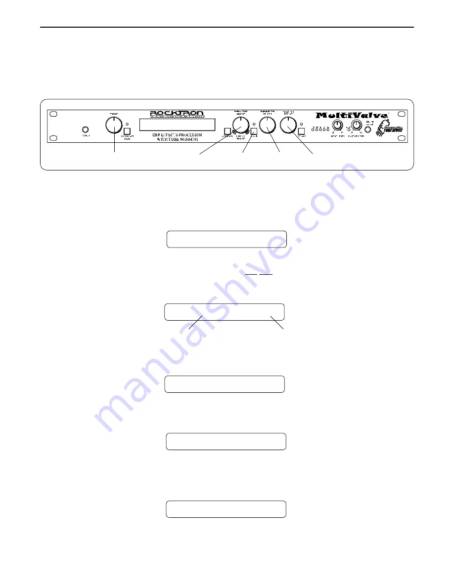
The Copy function allows you to copy any preset, preset title or controller assignment into any other preset location

instantly.

Step 1

Turn the FUNCTION SELECT control to "COPY".

SSSS


COPY 

SSSS

Turn the PARAMETER SELECT control one step clockwise to access the "PR> XX to >PR
XX" parameter, as shown below. The number on the left represents the preset to be copied,
while the number on the right represents the preset location to copy to.

Step 2

Operating the MultiValve

5

2

1

4

3

PR>    4      TO      >PR    4

Use the PRESET control to select the desired preset to be copied.

PR>    21      TO      >PR    4

Step 3

Preset location to copy to

Preset to copy

Use the PARAMETER ADJUST control to select the location to copy the selected preset
into.

Step 4

PR>    21      TO      >PR    59

Step 5

STORED

Press the STORE button to copy the selected preset into the selected preset location.
"STORED" will flash briefly on the display.

Copying presets:

Summary of Contents for MULTVALVE

Page 1: ...y one or more of the following U S Patents 4538297 4647876 4696044 4745309 4881047 4893099 5124657 5263091 5268527 5319713 5333201 5402498 5493617 and 5638452 Other patents pending Foreign patents pending USER S MANUAL ...

Page 2: ... should be immune from other sources of interfer ence when properly used Improper use of this equipment could result in increased RF emissions which may or may not interfere with other electronic products To insure against this possibility always use good shielded cables for all audio input and output connections Also bundle audio cables separately from the AC power cables These steps will help in...

Page 3: ...anged preset parameters 37 Switching Channels on Amplifiers and Preamps via the MultiValve 38 Editing a preset title 40 Controller Assignments 42 Copying MultiValve Presets Titles and Controller Assignments 46 Tap Delay 49 Program Changes 50 MIDI Channels 52 MIDI Dump Load 54 To dump a single MultiValve preset into another MultiValve 54 To dump a single MultiValve preset into a sequencer 56 To rel...

Page 4: ... need for a separate channel switching device Real Time Control of delay times and modulation rates through tap tempo and rate parameters Delay times and modulation rates can be changed instantly by tapping either a momentary footswitch or the front panel Tap Delay Rate parameter High quality digital effects include chorus delay auto pan tremolo rotating speaker pitch shift flanger reverb and phas...

Page 5: ...ITIONS TO THIS EQUIPMENT AT ANY TIME DO NOT TAMPERWITHINTERNALELECTRONICCOMPONENTSATANYTIME FAILURE TOFOLLOWTHESEINSTRUCTIONSMAYVOIDTHEWARRANTYOFTHISEQUIP MENT ASWELLASCAUSINGSHOCKHAZARD POWER REQUIREMENTS This unit accepts power from the 9VAC 3 4A adaptor supplied with the unit This 9 volt RMS AC voltage is internally processed by a voltage doubler which generates a bipolar 15 volts to maintain t...

Page 6: ...unction STEP 3 Turn the PARAMETER SELECT control to the parameter you wish to alter under the selected effect or utility function STEP 4 Use the PARAMETER ADJUST control to select the new parameter value STEP 5 The COMPARE button may be used to compare the sound of the altered value to the stored value STORING CHANGED PARAMETERS STEP 6 After the desired parameters have been edited press the STORE ...

Page 7: ...layed will cancel the previous altered value This will also occur if a MIDI control change is received while viewing the stored value s 6 PARAMETER ADJUST control This control is used to adjust the displayed parameter value When the parameter is altered from its stored value the LED above the STORE button will light until either a the new value is stored b a new preset is selected or c the paramet...

Page 8: ...evels when any other functions are displayed This will help you to guard against clipping the output of the mixer at the digital to analog converter 12 INPUT LEVEL control This control adjusts the unit s gain to match the signal level at the input of the MultiValve Use the INPUT LEVEL meter to determine the setting of this control 13 OUTPUT LEVEL control andCLIP LED This control is used to adjust ...

Page 9: ...ed during a performance or the need to run an extension cord out to the footswitch Instead of inserting the AC adaptor into the POWER jack of the footswitch as you would normally plug it into the PHANTOM POWER jack on the MultiValve This will power the Rocktron MIDI foot controller through pins 6 and 7 of the MIDI cable connecting the two units A 7 pin MIDI cable must be used and is available from...

Page 10: ...be chained together connected in series With more than 3 devices a slight distortion of the MIDI signal can occur due to signal degradation which can cause an error in MIDI signal transmission Should this problem arise a MIDI Thru box can be used which connects directly to the MIDI device which transmits MIDI information and has multiple connectors for the multiple devices receiving MIDI MIDI cabl...

Page 11: ...8 5 Connections Using the MultiValve within a guitar rack system ...

Page 12: ...9 Using the MultiValve in a preamp effects loop ...

Page 13: ...10 Using the MultiValve with a mixing console Connections ...

Page 14: ...s these effects HUSH Reverb Delay Parametric EQ Compression Phaser Flanger Tremolo Pitch Shift Chorus Auto Pan Speaker Simulator Rotary configuration provides these effects HUSH Reverb Delay Parametric EQ Compression Rotary Speaker Speaker Simulator Any of the effects provided within a particular configuration may be switched in or out for each preset Tube Mode In addition to the above effects the...

Page 15: ...12 Classic Configuration Block Diagram Block Diagrams ...

Page 16: ...13 Rotary Configuration Block Diagram Block Diagrams ...

Page 17: ...nction via the FUNCTION SELECT control then the list of available parameters for the selected function via the PARAMETER SELECT control and finally the adjustable value for each parameter via the PARAMETER ADJUST control Step 2 Turn to select a parameter within the selected function Step 1 Turn to select a function Step 3 Turn to alter the value of the selected parameter The remainder of this sect...

Page 18: ...or all presets This feature can be useful when switching from a quiet guitar with passive electronics to a noisy guitar with active electronics as the active guitar would require a higher Threshold level in all presets The MUTE parameter allows you to mute the output of the MultiValve This feature is especially useful when changing guitars during a live set When the MultiValve is muted front panel...

Page 19: ...meter determines the level of the direct signal of the current preset at the right output The EFFECT LEVEL parameter determines the volume of the overall effect signal Chorus Flange Pitch Shift etc level The DIRECT parameter determines whether the direct signal is pre HUSH or post HUSH When set to pre HUSH the direct signal is not passed through the HUSH circuitry or any other digital circuitry i ...

Page 20: ...ETER SELECT control will allow you to access each of the following Tube Mode parameter TUBE MODE Function TUBE MODE When set to BYPASS the input signal completely bypasses the tube circuitry When set to LOW the input signal is routed through the tube at a low gain setting resulting in subtle clipping When set to HIGH the input signal is routed through the tube at a higher gain setting resulting in...

Page 21: ...he output signal level relative to the input signal level As the input signal drops further below the threshold point downward expansion increases A drop in the input level by 20dB would cause the output level to drop approximately 40dB i e 20dB of gain reduction In the absence of any input signal the expander will reduce the gain so that the noise floor becomes inaudible The HUSH circuit is locat...

Page 22: ...urrent preset The COMPRESSOR THRESHOLD parameter determines the input level in dB at which compression will begin Lower settings of this parameter will result in more compression The COMPRESSOR ATTACK parameter determines the speed in milliseconds at which the compressor will reach its maximum com pression level after the input signal has exceeded the threshold level set by the COMPRESSOR THRESHOL...

Page 23: ... parameter determines a mid band center frequency between 250Hz and 2KHz to be cut or boosted via the MID LEVEL parameter The MID BANDWIDTH parameter determines in octaves the width of the selected mid band The TREBLE LEVEL parameter allows you to cut or boost the high band frequencies by up to 15dB The TREBLE FREQUENCY parameter determines a high band center frequency between 1KHz and 8KHz to be ...

Page 24: ...witched out If the output were not muted signals that were input before the delay was switched out would be allowed to regenerate even after switching out the delay It is also possible to mute both the input and the output BOTH so that no signal enters or exits the Delay section until it is switched in The TIME1 parameter determines the multiplier by which a new delay time will be selected for Del...

Page 25: ... 2 signal to the left or right channel The DELAY TIME2 parameter determines the length of time in milliseconds after the input signal that the Delay 2 signal will begin The DELAY TIME can be adjusted via the PARAMETER ADJUST control MIDI controller changes or via the Tap Delay feature The FINE 2 parameter allows for adjustment of Delay 2 in 1 millisec ond increments The DLY RGN 2 parameter determi...

Page 26: ...he length of time that the reverb signal will sound before it has completely died out The REVERB HIGH FREQUENCY DAMPING parameter is used to control the decay rate of high frequency information in the reverb signal Higher parameter settings will result in a faster decay of high frequency information The R SPILLOVER parameter determines whether reverbs generated in the current preset will continue ...

Page 27: ...rb configuration The TREMOLO DEPTH parameter determines the amount of modula tion for the Tremolo signal Lower DEPTH settings produce more subtle tremolo effects while higher settings will result in a more extreme tremolo effect The TREMOLO RATE parameter determines the speed at which the tremolo signal modulates or increases and decreases in volume The SHAPE parameter determines the waveshape of ...

Page 28: ...her parameter settings result in the sweep of the filtering effect occurring over a wider frequency range The RATE parameter determines the speed at which the phase shifted signal is modulated The PHASER RESONANCE parameter adds feedback to the Phaser so that it has a more pronounced effect The PHASER STAGES parameter determines how many stages of phase shift are to be active A parameter setting o...

Page 29: ...t The FLANGER RATE 1 parameter determines the speed at which Voice 1 is modulated The TIME1 parameter determines the multiplier by which a new modulation rate will be selected for the RATE 1 parameter when the Tap Delay feature of the MultiValve is used See Section 7 Tap Delay for more information on the Tap Delay feature The FLANGER OUTPUT 2 parameter determines the overall volume of Voice 2 The ...

Page 30: ...horter delay times will result in a tighter sounding chorused signal while longer delay times will produce a larger ambient effect The TIME 1 parameter determines the multiplier by which a new modulation rate will be selected for the RATE 1 parameter when the Tap Delay feature of the MultiValve is used The CHORUS OUTPUT 2 parameter determines the volume of Voice 2 This parameter allows you to pan ...

Page 31: ...o the left or right channel The PITCH parameter selects what harmony note the MultiValve will produce based on the input note The value displayed for this parameter represents the number of cents that the signal will be shifted adjustable in 20 cent increments Each 100 cents or five 20 cent steps above or below 0 represents the number of half steps the shifted signal will be from the input signal ...

Page 32: ...d One octave plus a Major 2nd One octave plus a minor 2nd 2 Octaves PARAMETER VALUE 1200 1100 1000 900 800 700 600 500 400 300 200 100 0 100 200 300 400 500 600 700 800 900 1000 1100 1200 1300 1400 1500 1600 1700 1800 1900 2000 2100 2200 2300 2400 NOTE There are 5 steps of the parameter adjust control between each of the intervals shown above each step equals 20 cents This allows for smooth pitch ...

Page 33: ...or bypassed for the current preset The LOCATION parameter determines what part of the signal path is affected by Auto Pan Direct Only Effects Only or Both The AUTO PAN RATE parameter determines the speed at which the signal is panned between the Left and Right channels The AUTO PAN WIDTH parameter determines the intensity at which the signal is panned between the Left and Right channels The TIME p...

Page 34: ...ED parameter switches between the SLOW SPEED and FAST SPEED setting The ROTARY SPEAKER SLOW parameter sets the slow rotation speed The horn and rotor will rotate at slightly different speeds The ROTARY SPEAKER FAST parameter sets the fast rotation speed The ROTARY SPEAKER ACCELERATION parameter adjusts how long it takes to reach the FAST SPEED or SLOW SPEED setting of both the horn and the rotor T...

Page 35: ...ent preset The SPEAKER TYPE parameter determines the type of speaker to be simulated 15 12 10 8 and full range speakers are available The MIC PLACEMENT parameter simulates a microphone placed anywhere from the center of the speaker cone out to the edge of the cone Positive parameter values simulate moving the microphone toward the center of the speaker while negative values move it to the edge The...

Page 36: ...DLYHFDAMP DELAYOUT1 DLYPAN1 Functions and Parameter Ranges Stereo Mono 10dB to 30dB Out In Out In to 6dB to 6dB to 6dB Pre Post Direct 0 to 100 Effect Direct 0 to 100 Effect Direct 0 to 100 Effect Direct 0 to 100 Effect 0 to 127 Bypass Low High Out In 90 to 27 In Out 30dB to 6dB 1ms to 75ms 05 to 2 seconds Out In 15dB to 15dB 63Hzto500Hz 2 to 2 octaves 15dB to 15dB 250Hzto2kHz 2 to 2 octaves 15dB ...

Page 37: ... RATE 1 TIME1 FLN OUT 2 FLN PAN2 FLN DPTH 2 FLN RATE 2 TIME2 FLN REGEN Functions and Parameter Ranges 0ms to 1000ms 0ms to 9ms to 0dB to 0dB Left 0 to 100 Right 0ms to 1000ms 0ms to 9ms to 0dB Off On Muted Active Effect 0 to 100 Delay to 0dB 0 to 99 0 to 99 Off On Out In Pre Rev Post Rev 0 to 100 0 to 254 Triangle Square 32nd 16th 8th Triplet or None Out In Left 0 to 100 Right 0 to 100 0 to 254 0 ...

Page 38: ... ROT BAL SPKR SIM I O SPKR TYPE MIC POSITION REACTANCE CHORUS PITCH SHIFT AUTO PAN ROTARY SPEAKER SPEAKER SIMULATOR Functions and Parameter Ranges Out In to 0dB Left 0 to 100 Right 0 to 100 0 to 254 0ms to 148ms 32nd 16th 8th Triplet or None to 0dB Left 0 to 100 Right 0 to 100 0 to 254 0ms to 148ms 32nd 16th 8th Triplet or None Out In to 0dB Left 0 to 100 Right 2400 to 1200 20 to 20 cents Slow Med...

Page 39: ...36 7 Operating the MultiValve Step 1 Turn the PRESET control to the desired preset you wish to recall The selected preset will be recalled automatically Selecting a preset 29 PRESET TITLE 1 ...

Page 40: ...o alter the parameter value The LED above the STORE button will light indicating that the preset has had a parameter altered from its stored value REV DECAY 32 Step 3 Step 2 Step 4 The COMPARE button may now be pressed to compare the sound of the stored parameter value to the sound of the altered parameter value REV DECAY 59 4 3 2 5 Storing changed preset parameters Step 5 While viewing a function...

Page 41: ...AMETER ADJUST control to select the on off condition of Channel Switch 1 When switched ON the channel connected to the Tip of the MultiValve CHANNEL SWITCH jack will be switched when the current preset is recalled CHAN SW 1 ON Step 2 Turn the PARAMETER SELECT control one step clockwise to CHAN SW 1 CHAN SW 1 OFF Step 1 Turn the FUNCTION SELECT control to CHANNEL SWITCHES CHANNEL SWITCHES 4 7 2 5 1...

Page 42: ...switched ON the channel which is connected to the Ring of the MultiValve CHAN NEL SWITCH jack will be switched when the current preset is recalled CHAN SW 1 ON Step 7 Press the STORE button to save the condition of Channel Switch 2 if changed STORED will flash briefly on the display STORED Step 4 Press the STORE button to save the condition of Channel Switch 1 if changed STORED will flash briefly ...

Page 43: ...r Use the PARAMETER ADJUST control to select the desired character for the current position flashing decimal Turn the PARAMETER SELECT control clockwise to initiate the Title Edit mode Turning this control will also select the character location to be edited A flashing decimal will follow the character currently selected Editing a preset title SS TITLE EDIT SS 57 P RESET TITLE 57 MR ESET TITLE 57 ...

Page 44: ...lashing STORED the MultiValve will remain in the Title Edit mode You may either a turn the PRESET control to display and edit other preset titles without having to exit and re enter Title Edit or b turn the FUNCTION SELECT control to exit the Title Edit mode STORED Step 5 After all the characters have been edited as needed press the STORE button to save the new title memory The MultiValve will fla...

Page 45: ...H parameter will be at 200 while at its toe position it will be at 300 Up to ten controllers can be assigned for each individual preset Operating the MultiValve Step 1 Step 2 To access the Controller Assign function turn the FUNCTION SELECT control clockwise to CONTROLLER ASSIG This parameter CTR A only also gives you the option of selecting ADJ When ADJ is selected the parameter assigned to the f...

Page 46: ...DJUST control to scroll through the available parameters for the current configuration Turn the PARAMETER SELECT control one step clockwise to display the parameter that is currently mapped to the CTR A control number After selecting the desired controller number press the STORE button to save the number for the CTR A parameter STORED will flash briefly on the display CTR A 7 STORED PA A BYPASS PA...

Page 47: ...e range from to 0dB yet you would like the range of the parameter to vary from only 12dB to 2dB you may set a lower limit of 12 and an upper limit of 2 via the Upper and Lower Limit parameters When a parameter is stored in the Controller Assign function Step 7 the maximum parameter value is automatically stored as the upper limit while the minimum value is stored as the lower limit Step 10 Step 11...

Page 48: ...of the expression controller will provide the minimum value while the heel position will provide the maximum value Note Steps 1 13 can be repeated nine times for a total of 10 controllers To exit Controller Assign at any time turn either the PRESET or FUNCTION SE LECT control Only those changes that have been stored will be saved after exiting the Controller Assign function After selecting a value...

Page 49: ...r on the left represents the preset to be copied while the number on the right represents the preset location to copy to Step 2 Operating the MultiValve 5 2 1 4 3 PR 4 TO PR 4 Use the PRESET control to select the desired preset to be copied PR 21 TO PR 4 Step 3 Preset location to copy to Preset to copy Use the PARAMETER ADJUST control to select the location to copy the selected preset into Step 4 ...

Page 50: ... PARAMETER SELECT or FUNCTION SELECT control to exit the preset copy function The preset has been copied to the new location but its title will be the title which was already at the new location STORED Copying preset titles Step 1 Turn the FUNCTION SELECT control to COPY SSSS COPYSSSS Turn the PARAMETER SELECT control two steps clockwise to access the TI XX to TI XX parameter as shown below The nu...

Page 51: ...ber on the right represents the preset location to copy those controller assignments to Step 2 Copying controller assignments CA 4 TO CA 4 Preset location to copy controller assgnments to Preset to copy controller assignments from Use the PRESET control to select the desired preset to copy controller assignments from CA 21 TO CA 4 Step 3 Use the PARAMETER ADJUST control to select the location to c...

Page 52: ...amount of time between taps The maximum delay time the MultiValve provides is 1000ms therefore the Tap Delay feature will automatically default to a lower TIME parameter value when the time between taps requires a delay time over 1000ms For example if the HALF setting is stored for the TIME 1 parameter and the time between taps is 600ms a delay time of 1200ms would be required i e 600ms x 2 Becaus...

Page 53: ... from Rocktron at a one to one correspondance i e MIDI program 1 is mapped to MultiValve preset 1 2 to 2 3 to 3 etc 4 8 3 7 1 2 5 6 Step 2 Turn the PARAMETER SELECT control one step clockwise to display the current Program Change On Map Off status PROGRAM CHANGES PROG CHANGES ON ProgramChangesstatusoptions ON Execute MIDI program changes as received by a MIDI controller MAP Use mapping table when ...

Page 54: ... 14 MAP TO 120 Step 7 The number on the right of the display is the preset number to map to or the preset number that will be recalled when the MIDI program number on the left is received Turn the PA RAMETER ADJUST control to select the preset number to map to 14 MAP TO 112 The preset number to map to can also be set to OFF thereby not responding to that program change command Step 8 After selecti...

Page 55: ...Valve displays MIDI CHANNELS MIDI CHANNELS Step 2 Turn the PARAMETER SELECT control one step clockwise to display the current MIDI Receive channel RECEV CHANL 1 Step 3 Turn the PARAMETER ADJUST control to select the desired MIDI channel You may select channels 1 16 OMNI all channels or OFF will not receive MIDI commands RECEV CHANL OMNI Step 4 Press the STORE button to save the new MIDI Receive ch...

Page 56: ...ram change on You may select channels 1 16 or OFF will not transmit a MIDI program change TRANS CHANL 1 Step 6 Press the STORE button to save the new MIDI Transmit channel STORED will flash briefly on the display STORED After the desired MIDI channels have been selected turn the FUNCTION SELECT control to exit the MIDI Channels function ...

Page 57: ...Operating the MultiValve Connect a standard MIDI cable from the MIDI OUT of the transmitting MultiValve to the MIDI IN on the receiving MultiValve Step 1 IMPORTANT Do not allow a looping connection from the MIDI OUT THRU of the receiving MultiValve back to the MIDI IN of the transmitting MultiValve Step 2 Turn the FUNCTION SELECT controls on both the transmitting and receiving MultiValves until MI...

Page 58: ...e STORE button on the transmitting MultiValve The transmitting MultiValve will display the preset number being dumped and DUMPED The receiving MultiValve will display the preset location being stored to and RECEIVING while it receives and stores the preset parameters and title 122 RECEIVING 32 DUMPED After all the information for the dumped preset is stored the receiving MultiValve will display LO...

Page 59: ...the sequencer s MIDI filter is set to accept SYSX information Connect a standard MIDI cable from the MIDI OUT of the transmitting MultiValve to the MIDI IN on the receiving sequencer Step 1 Step 2 Turn the FUNCTION SELECT controls on the transmitting MultiValve until MIDI DUMP LOAD is displayed Step 3 Turn the PARAMETER SELECT control on the transmitting MultiValve until BULK DUMP LOAD is displaye...

Page 60: ...tap delay information string 255 contains program mapping information and string 256 contains miscellaneous information Contact Rocktron Corporation for information on how to receive a detailed MIDI spec XXX DUMPED TRANSMITTING MULTIVALVE Step 6 After the MultiValve displays TRANS COMPLETE stop the sequencer The sequencer should have recorded all of the data that was dumped from the MultiValve Kee...

Page 61: ...allow a looping connection from the MIDI OUT THRU of the receiving MultiValve back to the MIDI IN of the transmitting sequencer Turn the FUNCTION SELECT controls on both the receiving MultiValve until MIDI DUMP LOAD is displayed MIDI DUMP LOAD RECEIVING MULTIVALVE Turn the PARAMETER SELECT controls on the receiving MultiValve until BULK DUMP LOAD is displayed MIDI DUMP LOAD RECEIVING MULTIVALVE St...

Page 62: ...ill display RECEIVE ERROR for transmis sion errors and XMEM ERROR for internal hardware errors Errors occurring in trans mission does not indicate that all of the received data is corrupted Only the transmission string where the error occurred is corrupted Y WhenreceivingaBulkLoad itisimportantthatthedataloadedtotheMultiValveisnottransmitted fasterthanitwasoriginallydumpedfromtheMultiValve Ifinfor...

Page 63: ...ESTORE Step 2 Turn the PARAMETER SELECT control one step clockwise to RESTR 1 TO 1 The number on the left is the original factory preset number to be restored The number on the right is the preset location that the preset will be stored into RESTR 1 TO 1 Factory preset to be restored Preset location to store into Step 3 Turn the PRESET control to select the factory preset to be restored RESTR 98 T...

Page 64: ...properly Any number of errors other than 0 means that the MultiValve may not have initialized properly and the process should be repeated CAUTION PressingtheSTOREbuttonatthistimewilloverwrite thecurrentpresetwiththedisplayedfactorypreset ERRORS 0 The MultiValve will remain in this condition until the FUNCTION SELECT control is turned to exit the Factory Restore function The preset currently recall...

Page 65: ...kwise to FACTORY RESTORE FACTORY RESTORE Step 2 Turn the PARAMETER SELECT control two steps clockwise to ALL RESTORE 0 ALL RESTORE 0 Step 3 A specific code number must be entered to restore the MultiValve memory Use the PA RAMETER ADJUST control to enter the number 243 ALL RESTORE 243 Operating the MultiValve 4 2 1 3 CAUTION Thisprocedurewillpermanentlyerasealluserpresets 1 128 andreplacethemwitht...

Page 66: ... properly and the process should be repeated ERRORS 0 The MultiValve will remain in this condition until the FUNCTION SELECT control is turned to exit the Factory Restore function The preset currently recalled will be the preset most recently restored into the current location The controller assignments for the MultiValve can also be reinitialized without affecting presets and other stored informa...

Page 67: ...called each time the unit is turned on The MultiValve allows you to store a Power On preset which will always be recalled when the unit is turned on 34 PRESET TITLE Press the STORE button while viewing the preset number and title to save it as the Power On preset PWR ON PR STORED Operating the MultiValve 2 1 ...

Page 68: ... remote connect the MIDI OUT of the All Access to the REMOTE jack of the MultiValve using a 7 pin MIDI cable as shown below Step 1 Step 2 Reinitialize the controller assignments as shown on page 62 under the heading Restoring the MultiValve Controller Assignments This will match up the MultiValve s controller assign ments to the All Access A code of 243 must be entered to initialize only the contr...

Page 69: ...ep 6 Press the STORE button to save the Remote on off status STORED will flash briefly REMOTE ON Step 7 If the MultiValve titles are to be displayed on the All Access turn the PARAMETER SE LECT control to TITLE XFER TITLE XFER OFF Step 8 Turn the PARAMETER ADJUST control to ON to enable title transfers from the MultiValve to the All Access display TITLE XFER ON Step 9 Press the STORE button to sav...

Page 70: ...ch 11 Allows you to bypass the MultiValve Switch 12 Switches the Reverb effect in or out Switch 13 Switches the Chorus effect in or out Switch 14 Switches the Delay effect in or out Switch 15 Instant Tap Delay access Pedal 1 Controls the Volume parameter Switch 6 Switches the EQ effect in or out Switch 7 No function Switch 8 Selects Slow or Fast Rotary speed Switch 9 Sends the change for Channel S...

Page 71: ...alve Upon proper setup and connection of the MultiValve and All Access units the All Access will provide the functions shown above when a Classic configuration preset is recalled Remote mode functions in Classic configuration ...

Page 72: ...nd connection of the MultiValve and All Access units the All Access will provide the functions shown above when a Rotary configuration preset is recalled Remote mode functions in Rotary configuration Operating the MultiValve ...

Page 73: ...for the current preset CONFIG SELECT Operating the MultiValve Step 2 Turn the PARAMETER SELECT control to access the XXXXXXX SELECTED param eter Step 3 Turn the PARAMETER ADJUST control to select the desired configuration ROTARY SELECTED Step 4 Press the STORE button to save the selected configuration STORED will flash briefly on the MultiValve display STORED CLASSIC SELECTED 4 3 1 2 ...

Page 74: ...TO CORRECTLY MIDI SYSTEM EXCLUSIVE INFORMATION WAS NOT RECEIVED CORRECTLY OR STORED CORRECTLY Corrective Action MAKE SURE EEPROM IS TIGHT IN SOCKET MAKE SURE WITHIN CORRECT OPERATING TEMPERATURE DISCONNECT MIDI CORD AT MIDI IN OF TRANSMlTTING MULTIVALVE BULK LOAD WAS TRANSMITTED TOO FAST CHECK SUM BYTE WAS NOT CORRECT DATA STRINGS NOT CORRECT LENGTH DATA STRINGS OUT OF ORDER MAKE SURE EEPROM IS TI...

Page 75: ... SYSTEM COMMON SYSTEM REAL TIME AUXILIARY MESSAGES TRANSMITTED 1 16 1 16 X X X X X X X X X X O O X X X X X X X X X RECOGNIZED 1 16 1 16 X X X X X X X X X O O O X X X X X X X X X REMARKS May be saved in non volatile memory For Bulk Dump Load and Preset Dump Load MultiValve Actual MIDI program value sent is 0 127 corresponding to presets 1 128 Optionalimplementationofprogrammappingalsoavailable The ...

Page 76: ...al Data MEASUREMENT Maximum Input 20dBu Maximum Output 20dBu Nominal Input Range 4dBu to 16dB Headroom 21dBu Input Impedance 470K ohms Output Impedance 120 ohms Dynamic Range 104dB HUSH IN 94dB HUSH OUT THD N 009 Dry Frequency Response 10Hz to 100kHz 25 2dB 10Hz to 30kHz 25dB Wet Frequency Response 20Hz 14 5kHz 5 3dB Rocktron Corporation 2870 Technology Drive Rochester Hills MI 48309 USA Customer ...

Reviews: