


Page 4 of 16
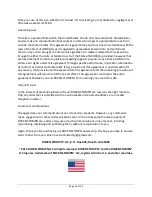
TOP PANEL
1 2 3 4
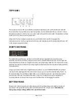
The top panel of your RS-4 provides four duplex receptacles, each with a dedicated red LED.
This instruction manual references each receptacle, and its dedicated LED, by number 1 thru 4. .
Receptacle number 1, first to turn on, and is next to the push button switch. Receptacle number
4,last to turn on, and is next to powercord.
Along side the four duplex receptacles is a push-button foot switch. It engages the
microprocessor to run the program which turns each receptacle and its dedicated LED on or off
in the proper sequential order.
RIGHT SIDE PANEL
The right side panel has two sections. On the left are two adjustable 16-position rotary
switches, one for the On Delay sequence and one for the Off Delay sequence. On the right are
three illustrations of how you might set a delay using the rotary switches. The 16 postion rotary
switches may also be refered to as rotary digital encoder which communicates directly with the
microprocessor.
Using any standard 1/8 inch straight blade screwdriver or your ROCKN STOMPN screwdriver
included in the poly bag with this instruction manual, you can set the desired delay from 1 to
15 seconds delay. You will feel a slight click as you rotate the actuator; each click represents
one second. There are no mechanical stops, so you can rotate the actuator clockwise or
counterclockwise as many times as you want without fear of damaging the switch.
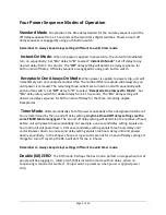
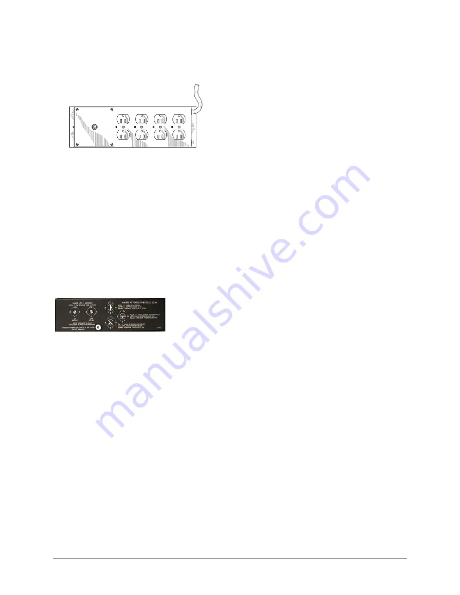
BOTTOM PANEL
Please note bottom panel quick refereance guide for setting delay and selecting modes of
operation. This quick referance guide and a screwdriver are all you need.
Remember to
always keep delays settings differant to avoid timer mode.