6
Fig. 8
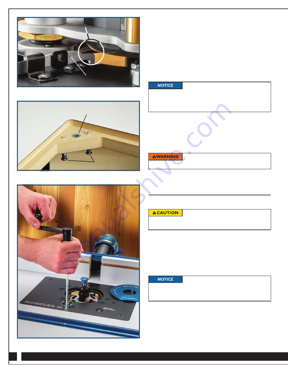
Fig. 6
Fig. 7
5.
Slide the motor into the lift carriage, stopping 1/8" before the
motor contacts the Insert Ring release arm.
Fig. 6.
If your
router has a height adjustment rack on the outside of the
motor housing, be sure to orient the router so the rack fits
in the opening in the carriage. If possible, rotate the motor so
that the on/off switch and variable speed controls will be easily
accessible to you when the lift is installed in your router table.
6.
Once your router is positioned in the carriage, make sure
you’ve maintained the clearance between the motor housing
and the Insert Ring release arm and tighten the socket-head
adjustment screw until the router cannot shift or slide. Then
tighten the locking nuts.
7.
Fit the SL Router Lift in the center opening of your router
table. It is sized to fit the 8
1
⁄
4
" x 11
3
⁄
4
" openings of Rockler and
Bench Dog router tables. Use the leveling screws that came
with your router table to bring the plate flush to the table on
all edges.
Fig. 7.
Then secure the lift to the table by using
the included M4 hex wrench to install the two included
1/4"-20 plate-mounting screws.
8.
Before use, snap the Insert Ring back into the plate’s
center opening.
Installing/Changing Router Bits
1.
Press the Snap-Lock Insert Release Button to pop the
aluminum Snap-Lock Insert Ring off the plate.
2.
Insert the Crank Handle in the dial in the lift plate. Turn the
crank clockwise to raise the carriage until the router collet
is fully accessible.
Fig. 8.
3.
Use the wrench(es) that came with your router to loosen the
collet, if necessary, and insert the desired bit in the collet. Let
it bottom out; then lift it 1/16" before tightening the collet. This
is to help ensure the collet is gripping the full shank of the bit.
4.
Use the crank handle to lower the bit, and then snap the
Insert Ring back into place.
5.
When you’ve achieved the height desired, remove the handle
and place somewhere off the work surface for safety.
If you are installing the SL Router Lift in
a custom table application, you will have to fabricate the
correctly sized opening yourself. Rockler offers a separate
template (20956, sold separately) to make this operation
easier and more accurate.
To “zero-out” the Fine-Adjustment dial,
spin the thumbwheel until the “0” lines up with the engraved
line on the plate. The socket must not turn during this step.
Fig. 9.
To avoid serious injury, never attempt to
cut a workpiece without an Insert Ring installed.
Do
NOT
use a cordless drill to raise
and lower the lift carriage. The resulting friction will cause
premature wear to the threads.
Leveling screws on
your router table
Threaded insert to accept 1/4"-20
plate mounting screws
Maintain gap
Insert Ring release arm


