9
8. Holding the table on its side, swing the outer legs back
so that they’re perpendicular to the back edge of the
table (forming an “L”).
Fig. 6.
9. Adjust the inside legs to fit the slot in each of its two Feet (3)
onto the cross bar of the outside legs.
Fig. 7.
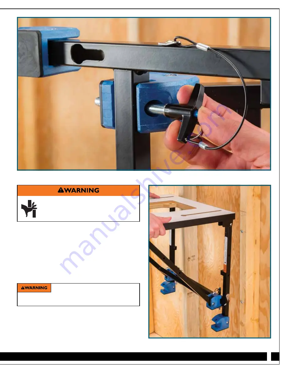
10. Pressing the buttons, install the Locking Pins in the holes in
the top of the Feet (3), through the cross bar and out the
bottom of the Feet. Release the buttons to secure the
Locking Pins.
Fig. 8.
>
To avoid pinching or crushing your fingers,
keep your hands away from the areas
where the legs cross.
Locking Pins MUST be installed correctly.
Failure to do so could result in serious injury and property
damage from the collapse of the router table.
11. Once the Locking Pins are secure, carefully lift the router
table and rotate the rear Feet (3) up and forward so that that
their back edges are flush with the back of the legs.
12. Fit the keyhole slots in the back of the outer legs over the
heads of the #14 Pan-Head Screws (14) you installed in the
wall studs or wooden stratchers.
Fig 9.
Fig. 9
Fig. 8


