


11
Rockford Systems, LLC—www.rockfordsystems.com
Call: 1-800-922-7533
DM
2
Series D Dual-Solenoid Valves
SECTION 5—INSTALLATION
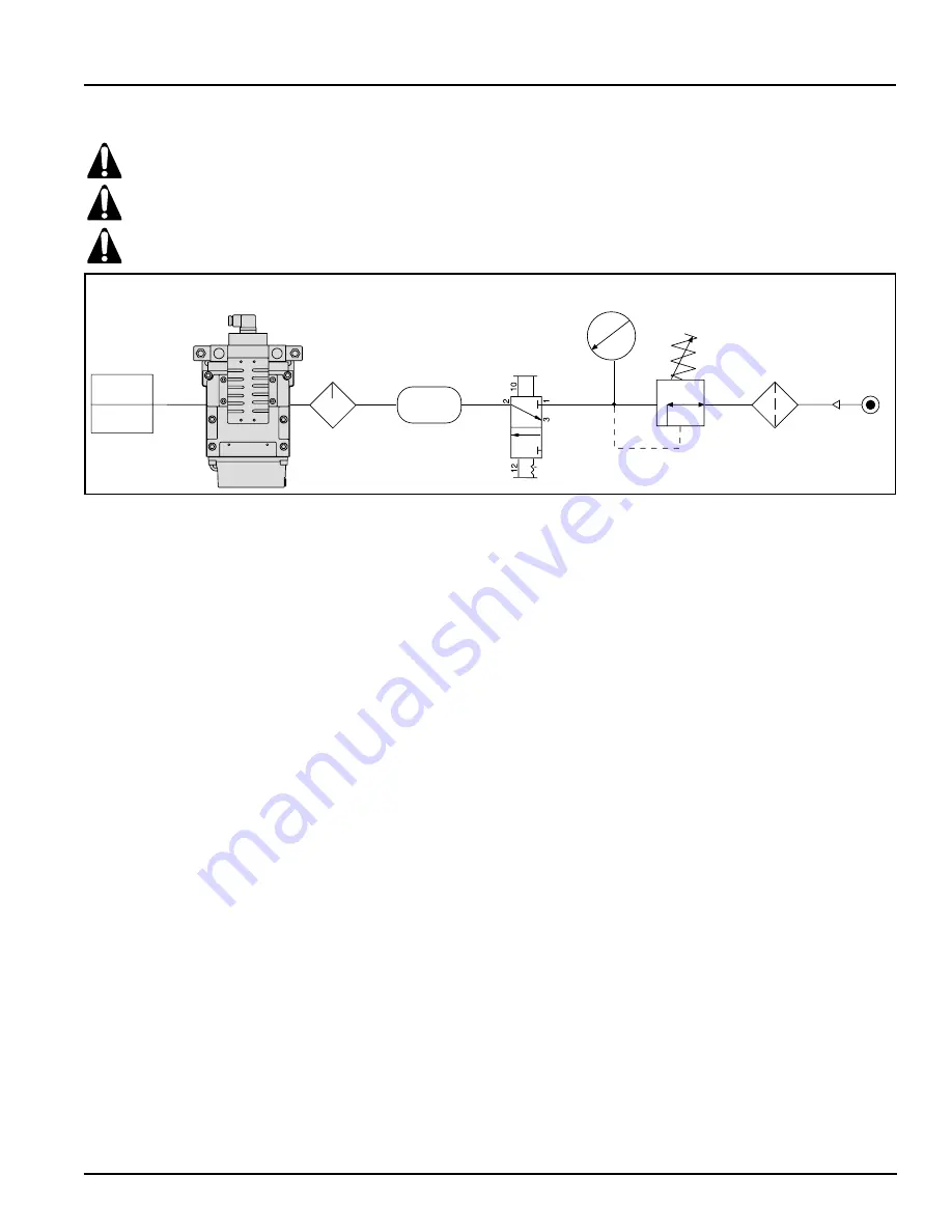
Pressure Regulator
Clutch and
Brake
Combination
Filter and
Water Separator
Pressure Gauge
Volume
DM
2
Series D Duel-Solenoid Valve
(Status Indicator – Optional)
Lubricator
Lockout Valve
Air Lines—Before installing this valve in a new or existing sys-
tem, the air lines must be blown clean of all contaminants. It is
recommended that a 5-micron-rated air filter be installed in the
inlet line close to the valve.
Valve Inlet (Port 1)—Be sure that the supply line is of adequate
size and does not have any restrictions (e.g., a crimp in the line,
a sharp bend, or a clogged filter element). The air supply must
not only provide sufficient pressure (see standard specifica-
tions, page 8), but must also provide an adequate flow of air
on demand. Otherwise, the valve elements will be momentarily
starved for air and the valve may fail to operate.
Valve Outlet (Port 2)—For faster pressurizing and exhausting
of the mechanism being operated by the valve, locate the valve
as close as possible to the mechanism. The lines must be of
adequate size and be free of restrictions (e.g., a crimp in the line,
a sharp bend, or a clogged filter element).
Valve Exhaust (Port 3)—Do not restrict the air flow from the ex-
haust port as this can adversely affect the operation of the valve.
The valves are factory equipped with a properly sized muffler.
Only the muffler furnished should be used.
Reset Port (RESET)—If your valve is not equipped with a reset
solenoid on the valve, then the RESET port should be supplied,
externally, from a 3/2 normally closed valve. The lines must be
of adequate size and be free of restrictions (e.g., a crimp in the
line, a sharp bend, or a clogged filter element). Reset signals
must be momentary.
Electrical Supply—DM
2
Series D dual-solenoid valves get elec-
trical power through plug-in connectors. The electrical supply
must correspond to the voltage and Hertz ratings of the sole-
noids. Otherwise, the solenoids are subject to early failure. If
power is supplied by a transformer, it must be capable of han-
dling the inrush current without significant voltage drop. See
standard specifications on page 8 for inrush current data.
Operating Pressures and Temperatures—Allowable ranges
for pressure and temperatures are given in the standard specifi-
cations on page 8. Exceeding these values can adversely affect
performance and shorten valve life.
Pipe Installation—To install pipe in base ports, engage the pipe by
one turn, then apply pipe thread sealant (tape not recommended),
and tighten pipe. This procedure will prevent sealant from entering
and contaminating the valve. To install pipe with parallel threads
(e.g., SAE, ISO 228-G, etc.) do not use sealant. After installing pipe
into the base ports, use compressed air to blow any debris out of
the piping, then install the valve onto the base.
Test—Always perform a test procedure after installation
and/or repair prior to normal use. Observe normal press op-
eration safety precautions during these tests to avoid personal
injury or damage to equipment. Note: Reset may need to be
performed prior to beginning the test procedure. Also, both
pilot solenoids must be de-energized prior to reset and must
remain de-energized until after the reset signal is removed.
Test Procedure—
1 . Electrically energize both pilot solenoids simultaneously,
then de-energize one pilot solenoid. This should result in a
valve lockout and prevent the valve from operating.
2 . Energize both solenoids and the valve should remain in the
lockout condition.
3 . De-energize both pilot solenoids and reset the valve.
4 . Electrically energize both pilot solenoids simultaneously
again. De-energize the other pilot solenoid this time. Again,
this should result in a lockout.
5 . Energize both pilot solenoids. The valve should remain in a
lockout condition.
6 . De-energize both pilot solenoids and then reset the valve.
After satisfying these tests, energizing both pilot solenoids si-
multaneously should result in normal operation.
Fault Indication—If fault indication is desired, Rockford Systems,
LLC offers a status indicator option that can be used to signal to
the press controls that a fault has occurred. The status indicator uti-
lizes a pressure switch. The pressure switch has four electrical con-
tacts. During normal operation, the pressure switch is pressurized.
A lockout condition depressurizes the switch until the valve is re-
set. Contacts 1 and 2 are closed when the switch is depressur-
ized (normally closed) and contacts 1 and 3 are closed when an
adequate pressure signal is applied to the switch (normally open).
Please read and make sure you understand all installation instructions before proceeding with the installation.
INSTALLATION CONSIDERATIONS
Pneumatic equipment should be installed only by persons trained and experienced in such installation.
The exhaust air muffler must be kept clean at all times. Never operate the machine unless the muffler is clean. The
muffler must be cleaned on a regular basis.


