Robur K18 Hybrigas Installation, Use And Maintenance Manual Download Page 39

First start-up 

Installation, use and maintenance manual – K18 Hybrigas 

39

5

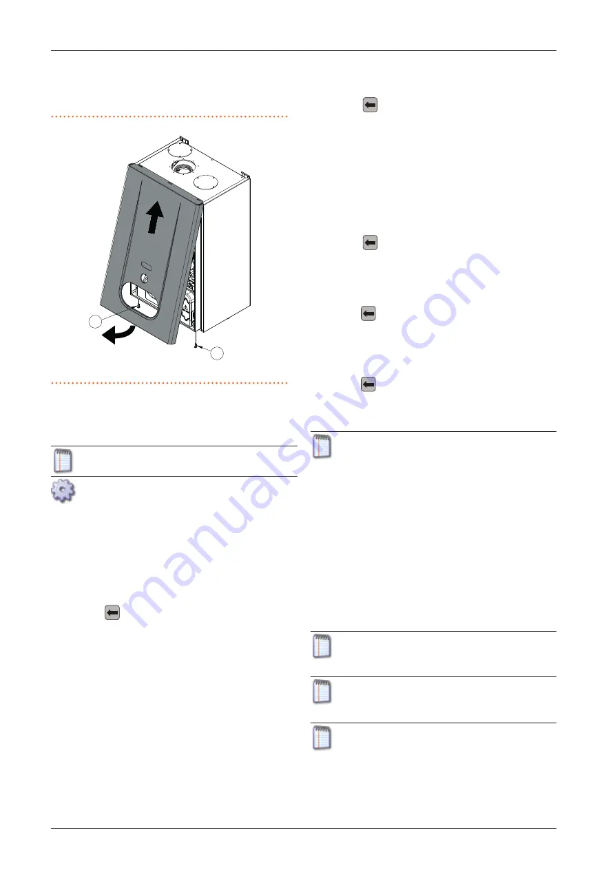
boiler front panel (detail 1 Figure 5.1 

p. 39);

3.   grab the front panel from the bottom and remove it pulling 

to yourself and then upwards (Figure 5.1 

p. 39).

Figure 5.1  

 Removal of the front panel of the boiler module

 Boiler front panel fastening screws

1

1

5.3 


 HEAT PUMP COMBUSTION PARAMETERS 

CHECK

Paragraph reserved exclusively to TACs.

Figure 5.2 

p. 40.

1.   If the appliance is running, switch it off with the applicable 

control system (OQLT019, OCDS007, external request).

2.   Remove the cap over the offset adjustment screw (C).

3.   Screw in completely the throttle adjustment screw (D).

4.   Screw in completely the offset adjustment screw (C).

5.   Unscrew the throttle adjustment screw (D) as indicated in 

Table 5.1 

p. 40.

6.   Unscrew the offset adjustment screw (C) as indicated in Ta-

ble 5.1 

p. 40.

7.   Press  the 

 key on the user interface of the heat pump 

module of the unit (detail B of Figure 1.14 

p. 20) for 5 sec-

onds to activate the chimney sweep function at minimum 

power.

8.   The display shows the letters "CS.LO" (chimney sweep low 

power), alternating with the flashing message "UAIt" (wait) 

which indicates that the machine is not yet ready for the 

reading.

9.   Once an approximate time ranging between 5 and 8 min-

utes elapses, the flashing message becomes "_GO_" to indi-

cate that the combustion control can be implemented.

10.  Ensure the CO

2

 value is between values indicated in column 

"Minimal thermal capacity" of Table 5.1 

p.  40. Otherwise 

set CO

2

 percentage reading by acting on the offset adjust-

ment screw.

11.  Press  the 

 key on the user interface again for 5 seconds 

to activate the chimney sweep function at maximum power.

12.  The display shows the letters "CS.HI" (chimney sweep high 

power), alternating once again with the flashing message 

"UAIt" (wait) which indicates that the machine is not yet 

ready for the reading.

13.  After a short while, the flashing message becomes "_GO_" 

again to indicate that the combustion control at maximum 

power can be implemented.

14.  Ensure the CO

2

 value is between values indicated in column 

"Nominal thermal capacity" of Table 5.1 

p. 40.

If the check is successful:
15. 
 Press  the 

 key on the user interface again for 5 seconds 

to deactivate the chimney sweep function and complete the 

procedure.

If the check is not successful:

16.  Set  CO

2

 percentage reading by acting on the throttle adjust-

ment screw.

17.  Press  the 

 key on the user interface again for 5 seconds to 

deactivate the chimney sweep function.

18.  Repeat points 7 to 10 to reactivate the chimney sweep func-

tion at minimum capacity; verify once again and if necessary, 

correct the CO

2

 value in these conditions by actuating the 

offset adjustment screw.

19.  Press  the 

 key on the user interface again for 5 seconds to 

activate the chimney sweep function at maximum capacity, 

and then again for 5 seconds to deactivate it and complete 

the procedure.

To ensure the chimney sweep function is executed prop-

erly, there must be adequate thermal load, otherwise the 

appliance could reach the maximum limit of the delivery 

and/or return temperature and then stop.

The following may be necessary to provide adequate 

thermal load, depending on the system characteristics:


„

 activate optional pumps or zone valves of the distribu-

tion water circuit;


„

 fully open the manual or thermostatic valves, mounted 

on the radiators;


„

 activate the ventilation of the fan coils and increase the 

setting of the optional thermostat placed on them.

Table 5.2 

p.  40 shows the messages that can appear on the 

display while the chimney sweep function is running, the rela-

tive meaning and the optional actions required.

Limit the time you use the chimney sweep function to 

the minimum actually required.

The system automatically interrupts chimney sweep 

function after 20 minutes from activation.

If the required CO

2

 settings cannot be reached, contact 

Robur.

Summary of Contents for K18 Hybrigas

Page 1: ...37 9 kW nominal thermal power for DHW 37 9 kW Hybrid system with gas absorption heat pump and condensing boiler for heating and buffer tank domestic hot water production K18 Hybrigas Installation Use...

Page 2: ...nd maintenance manual other than for personal consultation must be previously authorised by Robur S p A The rights of those who have legitimately filed the registered trademarks contained within this...

Page 3: ...drainage p 34 4 Electrical installer p 34 4 1 Warnings p 34 4 2 Electrical systems p 34 4 3 Electrical power supply p 35 4 4 Control system p 35 4 5 Alarm indicator lamp p 37 4 6 Remote the board err...

Page 4: ...her devices and with the user III WARNINGS III 1 GENERAL AND SAFETY WARNINGS Installer s qualifications Installation must exclusively be performed by a Qualified Firm and by Skilled Personnel with spe...

Page 5: ...anger Request assistance from the TAC Electrocution hazard Disconnect the electrical power supply before any work procedure on appliance components For electrical connections exclusively use compliant...

Page 6: ...l heating capacity up to 70 kW EN 378 Refrigerating systems and heat pumps UNI EN 483 Type C gas appliances with nominal thermal ca pacity not greater than 70 kW Other applicable provisions and standa...

Page 7: ...nk DHW production up to 80 C controlling secondary zone circuits via the system controller high thermal power heating capacity burned 29 2 kW delivered thermal power 37 9 kW indoor or outdoor versions...

Page 8: ...wer Active auxiliary boiler at full power E Heat pump off Active auxiliary boiler at full power 100 0 Tj 20 C A B C D E PLRh Tj In the presence of a minimal thermal demand scenario A the minimum power...

Page 9: ...egration of the thermal power of the heat pump module scenarios B C and D integration and replacement just like in the integration mode with the addition that in particular environmental conditions th...

Page 10: ...20 mm F Flue gas condensate and defrosting water discharge conveyor G Boiler display transparent cover which can be detached to access the user interface keys H Boiler reset unlock button I Heat pump...

Page 11: ...e and maintenance manual K18 Hybrigas 11 1 1 3 CONNECTION PLATE DETAIL Figure 1 4 Connection plate detail A Water outlet connection 3 4 M B Water inlet connection 3 4 M F Boiler module safety valve di...

Page 12: ...Features and technical data 12 1 1 4 COMPONENTS Figure 1 5 LH front view A Heat pump module B Boiler module B A...

Page 13: ...p module internal components 1 Fan 2 Flame sensing ignition electrodes 3 PT1000 flue exhaust temperature probe 4 Limit thermostat 5 Defrosting valve 6 TA outdoor temperature probe 7 Teva evaporator te...

Page 14: ...components rear view 1 Safety valve 2 Flowmeter 3 Heat pump module flue gas exhaust 4 Condensate discharge 5 Condensate level sensor 6 Water outlet connection 3 4 M 7 Water inlet connection 3 4 M 8 R...

Page 15: ...nd maintenance manual K18 Hybrigas 15 1 Figure 1 8 RH front view heat pump module internal components 1 Gas valve 2 Combustion blower 3 Ignition transformer 4 Oil pump 5 TG generator temperature probe...

Page 16: ...d technical data 16 1 Figure 1 9 LH side view A Boiler module flue gas exhaust outlet B Heat pump module flue gas exhaust outlet C Socket for boiler flue gas analisys D Boiler module combustion air in...

Page 17: ...gure 1 10 Detail of water pipes connection between boiler module and connection plate A Heating water outlet pipe B Heating water inlet pipe G Gas pipe S Space heating water delivery temperature probe...

Page 18: ...nsor LS Gas valve ON indicator lamp GV Gas solenoid valve TC Manual flue gas thermostat TL Generator limit thermostat FM Flowmeter CWS Condensate water sensor VD Defrosting valve FAN Fan THMC Hot wate...

Page 19: ...onnector for optional outdoor temperature probe MP Control panel terminal block L Line N Neutral ne Black gi ve Green yellow bl Blue ro Red ce Light blue ma Brown ar Orange gi Yellow bi White gr Grey...

Page 20: ...ectronicBoardGHP10withmicroprocessor itcontrolsthe appliance and displays data messages and operative codes The appliance is monitored and programmed by interacting with the display and selection keys...

Page 21: ...ol of one K18 Hybrigas unit with variable water setpoint according to heating curves and type of DHW function room comfort control by controlling two heating circuits of which one optionally of mixed...

Page 22: ...ature maximum for DHW C 70 3 DHW inlet temperature maximum for DHW C 60 3 Electrical specifications Power supply voltage V 230 type single phase frequency 50 Hz supply 50 Electrical power absorption n...

Page 23: ...h 2000 minimum l h 400 Electrical specifications Electrical power absorption nominal kW 0 35 Installation data Gas consumption methane G20 nominal m h 1 20 1 GPL G30 G31 nominal kg h 0 87 2 General i...

Page 24: ...ly remove the packing after placing the appliance on site Do not leave parts of the packing within the reach of chil dren plastic polystyrene nails since they are potentially dangerous Weight The lift...

Page 25: ...air flow reaching the finned coil and leaving the front part of the appliance or with the fumes exhaust The appliances flue gas exhaust must not be immediately close to openings or air intakes of buil...

Page 26: ...ems flue gas exhaust flue gas condensate discharge Installation must also comply with the manufacturer s provisions 3 2 INSTALLATION 3 2 1 Primary and secondary heating circuit The K18 Hybrigas applia...

Page 27: ...gas EVO hydraulic diagram Figure 3 2 K18 Hybrigas EVO 1 heat pump condensing boiler K18 Hybrigas 2 modulating internal water pumps with available head of 2 0 m w c 3 anti vibration connection 4 pressu...

Page 28: ...overpressure valve calibrated to open only when both valves 3 are closed 3 2 way valve 4 radiator 5 system controller required optional OQLT019 6 advanced room unit standard 7 advanced room unit avai...

Page 29: ...E A 5 Heating distribution with up to three heating circuits two of which are optionally mixed and one not mixed system with primary and secondary water circuits Figure 3 6 Heating distribution 04 sys...

Page 30: ...on activated by default automatically starts the primary circula tion pump and if required the burner too when the outside temperature approaches zero Electrical and gas continuity The active anti ici...

Page 31: ...r the appliance the system the environment and health Contact specialised firms or professionals for water treat ment or system washing Check compatibility of treatment or washing products with operat...

Page 32: ...pply pressure both static and dynamic must comply with Table 3 3 p 32 with tolerance 15 Non compliant gas pressure Table 3 3 p 32 may damage the appliance and be hazardous Table 3 3 Gas network pressu...

Page 33: ...stallation data Percentage CO2 in fumes Nominal thermal capacity G20 9 44 G30 11 10 G31 10 20 Minimal thermal capacity G20 9 04 G30 10 50 G31 10 05 Flue temperature Nominal thermal capacity G20 C 73 7...

Page 34: ...I p 4 providing im portant information on regulations and on safety Compliance with installation standards Installation must comply with applicable regulations in force based on the installation Count...

Page 35: ...g terminals and liquid penetration at least the protection index IP 25 declared for the unit must be guaranteed The unused holes for cables passage must remain cov ered by caps 4 Insert cables through...

Page 36: ...ee also Paragraph 1 8 p 21 It is required to arrange request device e g thermostat clock button fitted with a voltage free NO contact How to connect the external request Connection of external request...

Page 37: ...to the terminal block in the Electrical Panel inside the appliance Connect the button as instructed below Figure 4 7 p 37 1 Access the connection terminal block according to Proce dure 4 2 p 34 2 The...

Page 38: ...for the re quired capacities and equipped with all safety and control devices required by the regulations in force absence of leaks in the water and gas systems type of gas for which the appliance is...

Page 39: ...ine is not yet ready for the reading 13 After a short while the flashing message becomes _GO_ again to indicate that the combustion control at maximum power can be implemented 14 Ensure the CO2 value...

Page 40: ...thermal load before reactivating the function Err The appliance switched off due to an anomaly Warning or Error Deactivate the function by pressing the key for 5 seconds and then intervene according...

Page 41: ...T START UP Paragraph reserved exclusively to TACs The instructions on the use of the GHP10 electronic board concern the firmware version 1 012 For the use of GHP 10 electronic board and related menu s...

Page 42: ...urve for space heating from 0 C to 40 C 20 1 If modulation of circulation pump in space heating mode is not active i e parameter 174 set to 0 2 If modulation of circulation pump in DHW mode is not act...

Page 43: ...antaneous value as the outdoor temperature Integration and replacement mode on space heating service If the control mode of the boiler module is integration and re placement parameter 50 set to 3 by d...

Page 44: ...restart a locked down unit refer to Paragraph 6 6 p 49 5 6 SETTING PARAMETERS FOR BOILER FIRST START UP To access the parameters menu and set their values follow the procedure below refer to Figure 5...

Page 45: ...l Figure 1 15 p 21 Make sure that the boiler is ON on space heating service To do this proceed as follows 1 press key to select desired operating mode summer mode space heating only mode winter mode O...

Page 46: ...mediately but it will only start when there are actual service demands 6 3 MESSAGES ON THE HEAT PUMP DISPLAY 4 digit display The GHP10 board of the appliance Paragraph 1 6 p 20 is equipped with a 4 di...

Page 47: ...terest by pressing key the dis play will show the current parameter value blinking or for a command menu a blinking code eg rEr1 for the board error reset command 7 Press the key to reconfirm the figu...

Page 48: ...e is lower in this case the slope of the curve is not sufficient it is needed to set a higher value for parameter 228 indicating the slope of the curve Internal ambient temperature is higher when the...

Page 49: ...e three options for resetting a fault 1 If the appliance is connected to the OQLT019 controller you may act through the control device as described in the rel evant manual 2 If a remote reset button h...

Page 50: ...HEATING TEMPERATURE SETTING Do not change space heating setpoint set on the boiler during first startup 6 9 EFFICIENCY For increased appliance efficiency Keep the finned coil clean Set the maximum wat...

Page 51: ...onment etc maintenance and cleaning op erations must be more frequent 7 2 PRE EMPTIVE MAINTENANCE 7 2 1 Heat pump module For pre emptive maintenance comply with the recommendations in Table 7 1 p 51 T...

Page 52: ...How to deactivate the appliance for long periods of time 1 Switch the appliance off Paragraph 6 2 p 46 2 Only when the appliance is completely off power it off with the main switch disconnector switch...

Page 53: ...To exit the menu 2 and return to the main screen 7 Press button until the rightmost digit shows letter E Exit then press button 8 Press again button until the leftmost shows letter E Exit then press...

Page 54: ...de persists shows up again or in case of doubt contact the TAC 408 Flame controller error NA Contact the TAC 410 Low hot water flow Reset is automatic when the triggering condition ceases Check and cl...

Page 55: ...h 6 6 1 p 49 If the code persists shows up again or in case of doubt contact the TAC 442 Flame loss Reset occurs automatically 10 seconds after the code is generated NA 443 Flame controller communicat...

Page 56: ...the code persists shows up again or in case of doubt contact the TAC E02 RESET Safety thermostat 95 C Press the reset button detail H Figure 1 3 p 10 As soon as the error code disappears from the disp...

Page 57: ...mperature and ambient temperature Blinking red light Pump out of order Pump blocked Pump does not restart autonomously Replace the pump OFF No power supply No voltage on electronics The unit has never...

Page 58: ...37 2 kW Seasonal space heating energy efficiency s 131 Tj 6 C Pdh 26 4 kW Tj 6 C PERd 120 Tj 8 C Pdh 21 2 kW Tj 8 C PERd 136 Tj 10 C Pdh 16 0 kW Tj 10 C PERd 140 Tj 12 C Pdh 10 8 kW Tj 12 C PERd 141 T...

Page 59: ...utdoors __ 4000 m h Sound power level indoors outdoors L WA 65 dB For water or brine to water heat pumps Rated brine or water flow rate outdoor heat exchanger __ m h Additional information required by...

Page 60: ...d promotion of safe environmentally friendly energy efficiency products through the commitment and caring of its employees and partners Robur mission Robur S p A advanced technologies for climate cond...

Reviews: