RoboteQ CANBus Series User'S Reference Manual Download Page 27

Use and benefits of CANopen


                 CANBus Networking Manual 

27

SECTION 3 

CANopen 
Interface

This section describes the configuration of the CANopen communication protocol and the 
commands accepted by the controller using the CANopen protocol. It will help you to en-
able CANopen on your Roboteq controller, configure CAN communication parameters, and 
ensure efficient operation in CANopen mode. 

The section contains CANopen information specific to Roboteq controllers. Detailed information 
on the physical CAN layer and CANopen protocol can be found in the DS402 documentation.

Use and benefits of CANopen

CANopen protocol allows multiple controllers to be connected into an extensible unified 
network. Its flexible configuration capabilities offer easy access to exposed device param-
eters and real-time automatic (cyclic or event-driven) data transfer.

The benefits of CANopen include:

• 

Standardized in EN50325-4

• 

Widely supported and vendor independent

• 

Highly extensible

• 

Offers flexible structure (can be used in a wide variety of application areas)

• 

Suitable for decentralized architectures

• 

Wide support of CANopen monitoring tools and solutions 
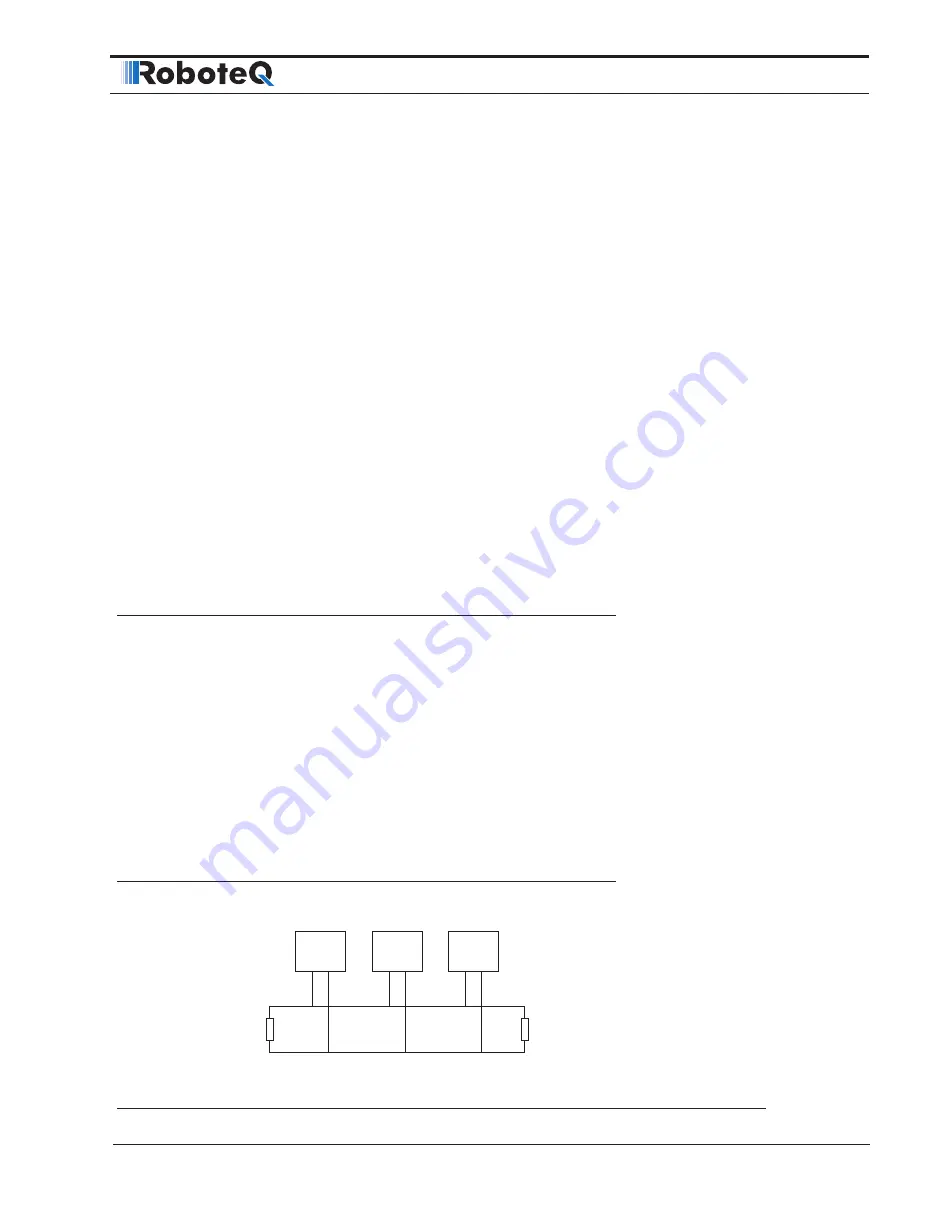
CAN Connection

CANH

CANL

120 Ohm
Termination
Resistor

120 Ohm

Controller

Controller

Other

CAN Device

FIGURE 3-1.   CAN connection

Summary of Contents for CANBus Series

Page 1: ...1 CANBus CANOpen RawCAN MiniCAN RoboCAN User Reference Manual V2 0 July 8 2019 visit www roboteq com to download the latest revision of this manual Copyright 2016 2019 Roboteq Inc...

Page 2: ...s July 8 2019 2 0 Extracted from main User Manual The information contained in this manual is believed to be accurate and reliable How ever it may contain errors that were not noticed at the time of p...

Page 3: ...d Frames 12 Reading Raw Received Frames 13 Transmitting Raw Frames 13 Using MiniCAN Mode 14 Transmitting Data 14 Receiving Data 14 MiniCAN Usage Example 15 SECTION 2 RoboCAN Networking 17 Network Oper...

Page 4: ...43 Abbreviations 43 Introduction 43 What is DS402 43 Implementation 44 Index Range Channel Selection 44 Modes of Operation 44 Supported SDOs 45 PDS FSA 45 SDO Description 47 0x6040 Control Word 47 0x6...

Page 5: ...tery or and Motor Amps sensing Storage size of user variables to Flash or Battery backed RAM User Manual Structure and Use The user manual discusses issues that are common to all controllers inside a...

Page 6: ...describes the configuration of the CANopen communication protocol and the commands accepted by the controller operating in the CANopen mode SECTION 4 DS402 Implementation on Roboteq Motor Controllers...

Page 7: ...tly simplified subset of CANopen allowing within limits the integration of the controller into an existing CANopen network This mode requires MicroBasic script ing to prepare and use the CAN data CANo...

Page 8: ...k communication will take place with a single resistor of 100 to 200 ohm located anywhere on the network Communication will not work if no resistor is present or if its value is too high No ground con...

Page 9: ...1 1 1 Figure 1 2 CANbus signaling Differential signaling reduces noise coupling and allows for high signaling rates over twist ed pair cable The High Speed CANbus specifications ISO 11898 Standard are...

Page 10: ...d USB Limitations On some controller models CAN and USB cannot operate at the same time On control lers equipped with a USB connector if simultaneous connection is not allowed the con troller will ena...

Page 11: ...nu ous stream of data frames This will cause the CANH voltage to rise above and the CANL voltage to drop below the 2 5V midpoint If the idle and active voltages do not match the above try again on the...

Page 12: ...or not by changing the Listen NodeID parameter that is shared with the MiniCAN mode A value of 0 will capture all incoming frames and it will be up to the user to use the ones wanted Any other value...

Page 13: ...t than 0 then a new frame has arrived and you may read the data After reading the header its value will be 0 if read again unless a new frame has arrived New CAN frames will not be received by the con...

Page 14: ...dRate configuration parameter Header TPDO1 0x180 NodeID TPDO2 0x280 NodeID TPDO3 0x380 NodeID TPDO4 0x480 NodeID Data Byte1 Byte2 Byte3 Byte4 Byte5 Byte6 Byte7 Byte8 TPDO1 VAR1 VAR2 TPDO2 VAR3 VAR4 TP...

Page 15: ...shown in the table above with the lowest Boolean Variable occupying the least significant bit of each byte Example a received byte of 0x01 will set Boolean Var 33 and clear Vars 34 to 40 MiniCAN Usag...

Page 16: ...CAN Networking on Roboteq Controllers 16 CANBus Networking Manual V2 0 July 8 2019...

Page 17: ...ational data from any other node on the network One or more controller can act as a USB to CAN or Serial to CAN gateway allowing several controllers to be thus managed from a single PC or mi crocomput...

Page 18: ...e node as a 2 digit hex address a command or query is sent to the desired node This scheme works with every Command Character Query Configuration setting Configuration read and most Maintenance comman...

Page 19: ...ng on the selected bit rate the reply may come up to 10ms after the query was sent Remote Queries restrictions Remote queries can only return a single value whereas local queries can be used to read a...

Page 20: ...ite can be broadcast to all nodes simultaneously by using the node Id 00 For example 00 OVL 250 Will set the overvoltage limit of all nodes at 25 0 Volts Configuration reads cannot be broadcast See th...

Page 21: ...ve been added to the MicroBasic language in order to easily send commands to and read data from any other node on the network Functions are also available to read and write configurations at a remote...

Page 22: ...t step can be done using one of the 3 following ways 1 Pause script execution for a few milliseconds using a wait instruction in line 2 Perform other functions and read the results a number of loop cy...

Page 23: ...r from a given node and make the value available for read ing without the need to send a Fetch command A function is provided to initiate the automatic sending of a value from the remote node at a spe...

Page 24: ...then read with the function ReadScannedCANValue aa Where aa is the location in the scan buffer The function returns an integer value If no new value was received since the previous read the old value...

Page 25: ...e value Self Addressed Commands and Queries Functions addressed to the local node have no effect The following function will not work if executed on node 4 SetCANCommand 04 _G 1 500 The regular functi...

Page 26: ...RoboCAN Networking 26 CANBus Networking Manual V2 0 July 8 2019...

Page 27: ...n be found in the DS402 documentation Use and benefits of CANopen CANopen protocol allows multiple controllers to be connected into an extensible unified network Its flexible configuration capabilitie...

Page 28: ...n network device must have a unique Node ID between 1 and 127 The val ue of 0 is used for broadcast messaging and cannot be assigned to a network node Bit Rate The CAN bus supports bit rates ranging f...

Page 29: ...pen specification Service Data Object SDO Read Write Messages Runtime queries and runtime commands can be sent to the controller in real time using the expedited SDO messages SDO messages provide gene...

Page 30: ...ser VAR 3 0x2106 4 User VAR 4 TPDO3 0x2106 5 S32 User VAR 5 0x2106 6 User VAR 6 TPDO4 0x2106 7 S32 User VAR 7 0x2106 8 User VAR 8 S32 signed 32 bit word Receive Process Data Object RPDO Messages RPDOs...

Page 31: ...ate but then it is necessary to avoid inconsistencies in the PDO mapping on the producer and the consumer side To avoid this the PDO must not be pro duced until the entire reconfiguration is finished...

Page 32: ...3 00 18 01 81 01 00 40 PDOTransmissionType The transmission type of a PDO can be set via the second sub index 0 1 The Transmit PDO is synchronous Which specific SYNC Object occurrence triggers the tra...

Page 33: ...ronous PDOs received by a node only become valid on arrival of the next Sync message In order that the bus is not blocked up by a large number of synchronous PDOs which are all sent with every Sync me...

Page 34: ...top in all modes U8 WO Yes MS 0x200F 01 mm 1 Set Pos Relative S32 WO Yes PR 0x2010 01 mm 1 Set Next Pos Absolute S32 WO Yes PX 0x2011 01 mm 1 Set Next Pos Relative S32 WO Yes PRX 0x2012 01 mm 1 Set Ne...

Page 35: ...T 0x2110 01 mm 1 Read Feedback S16 RO Yes F 0x2111 00 Read Status Flags U16 RO Yes FS 0x2112 00 Read Fault Flags U16 RO Yes FF 0x2113 00 Read Current Digital Outputs U16 RO Yes DO 0x2114 01 mm 1 Read...

Page 36: ...unter S32 RO Yes CSS 0x213F 01 si 10 Read SSI Relative Counter S32 RO Yes CSR 0x2141 00 Read BMS State of Charge U8 RO Yes BMC 0x2142 00 Read BMS Status Flags U8 RO Yes BMF 0x2143 00 Read BMS Operatio...

Page 37: ...00 Target Torque CH1 S16 RW Yes TC 0x6077 00 Torque Actual Value CH1 S16 RO Yes TRQ 0x607A 00 Target Position CH1 S32 RW Yes POS 0x6081 00 Profile Velocity CH1 U32 RW Yes PSP 0x6083 00 Profile Accele...

Page 38: ...Demand CH3 S16 RO Yes RMP 0x7044 00 VL Velocity Actual Value CH3 S16 RO Yes F 0x6046 01 VL Velocity Min Amount CH3 U32 RW Yes SPL 02 VL Velocity Max Amount CH3 U32 RW Yes SPL 0x6048 01 Velocity Accele...

Page 39: ...accessed subindex is the subindex of the object dictionary variable data contains the data to be uploaded The Response from the roboteq device is as shown below Header DLC Payload Byte0 Byte1 2 Byte...

Page 40: ...2 since it is a command n 3 since only one byte of the data is used unsigned8 index 0x200C and subindex 0x00 according to object dictionary Header DLC Payload Byte0 Byte1 2 Byte 3 Bytes4 7 bits 4 7 b...

Page 41: ...00 00 The respective response will be nd 1 since the source node id is 1 ccs 4 since it is a query response n 2 since 2 bytes of the data are used unsigned16 index 0x210D and subindex 0x02 according...

Page 42: ...CANopen Interface 42 CANBus Networking Manual V2 0 July 8 2019...

Page 43: ...de PV Profile Velocity Mode RO Read Only RW Read Write SDO Service Data Object TQ Torque Mode VL Velocity Mode Introduction This documentation will describe the implementation of CiA DS402 standard on...

Page 44: ...Closed Loop Speed controls Speed using Speed as feedback C Closed Loop Speed Position controls Speed using Position as feedback D Closed Loop Count Position controls Position E Closed Loop Position R...

Page 45: ...tion Display AOM 606400 Position actual value F 606C00 Velocity actual value F 607100 Target torque TC 607700 Torque actual value A 607A00 Target position POS 608100 Profile velocity PSP 608300 Profil...

Page 46: ...finite state machine while Table 4 3 describes the actions and the events of the transitions FIGURE 4 2 Power Drive System Finite State Automation TABLE 4 3 Transition Events and Actions Transition Ev...

Page 47: ...d The drive function shall be disabled 13 Fault Signal None 14 Automatic Transition The drive function shall be disabled 15 Fault Reset Command The drive function shall be enabled SDO Description 0x60...

Page 48: ...n enabled Profile Position Mode TABLE 4 8 control word mapping in profile position mode 15 10 9 8 7 6 5 4 3 0 see Table 4 4 Change on set point Halt see Table 4 4 Abs rel Change Set Immediately New Se...

Page 49: ...the bits that are independent to operation mode TABLE 4 12 Status Word Sub Index 00 Optional N Type U16 Access RO PDO T Value Range Discrete Default RoboCommand SW Description The status of the PDS F...

Page 50: ...lt bit 8 in controlword 1 Axis decelerates 1 Halt bit 8 in controlword 0 Speed or Position Target reached Halt bit 8 in controlword 1 Velocity of axis is 0 Profile Position Mode TABLE 4 16 Status word...

Page 51: ...n 0x6043 VL Velocity Demand Table 21 gives a short description of the object TABLE 4 21 Velocity Demand Sub Index 00 Optional N Type S16 Access RO PDO T Value Range Default RoboCommand RMP Description...

Page 52: ...he configured minimum and maximum amount of velocity in RPM The vl velocity max amount sub object shall be mapped internally to the vl velocity max positive and vl velocity max negative values The vl...

Page 53: ...on The requested operation mode 0x6061 Modes of Operation Display Table 4 27 gives a short description of the object and Table 1 shows the available modes TABLE 4 27 Modes of Operation Display Sub Ind...

Page 54: ...31 Torque Actual Value Sub Index 00 Optional CND Type S16 Access RO PDO T Value Range Default RoboCommand TRQ Description This object shall provide the actual value of the torque in Nm 100 It shall co...

Page 55: ...Access RW PDO R Value Range Default MAC 20000 RoboCommand PAC Description This object shall indicate the configured acceleration in RPM 10 second 0x6084 Profile Deceleration PP Table 4 35 gives a shor...

Page 56: ...BLE 4 38 Supported Drive Modes Sub Index 00 Optional REQ Type U32 Access C PDO N Value Range Default 0x0000000F RoboCommand SDM Description The supported drive modes Roboteq Controllers support Profil...

Reviews: