


RS-Helios-1610 User Manual
12
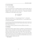
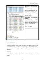
5.2 Point Cloud Display
5.2.1 Coordinate Mapping
Since the data packet output by the LiDAR only provides the horizontal rotation angle and
distance parameters, in order to present a 3D point cloud image, the angle and distance
information in polar coordinates need to be converted into x, y, z coordinates in the Cartesian
coordinate system, and the conversion formula is as follows:
� = � ��� ( �) ��� ( �);
� = � ��� ( �) ��� ( �);
� = � ��� ( �);
Where is the measured distance,
is the vertical angle of the laser,
is the horizontal
rotation angle of the laser in the Polar Coordinate System, and x, y, z are the coordinate values in
the Cartesian Coordinate System.
Note 1: ROS source code of RS-Helios-1610 has by default completed the coordinate conversion to conform to the
right-handed coordinate system of ROS. The X-axis of ROS is the positive Y direction in Figure 1, and the Y-axis of
ROS is the negative X direction in Figure 1.
Note 2: The origin of the LiDAR sensor coordinate is 63.5mm above the LiDAR base, on the center axis.
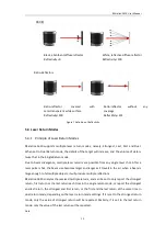
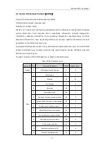
5.3 Reflectivity
RS-Helios-1610 measures the reflectivity of objects. The reflectivity is an index that measures the
ability of an object to reflect light and is greatly related to the material of the object itself.
Therefore, the reflectivity information can be used to distinguish objects of different materials.
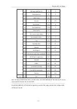
RS-Helios-1610 reports calibrated reflectivity values from 0 to 255, among which diffuse
reflectors report values from 0 to 100, and retroreflectors report values from 101 to 255. Black
objects are with low reflectivity values, white objects are with high reflectivity values, the most
ideal reflection reports the reflectivity value of 255.
Diffuse Reflectors


