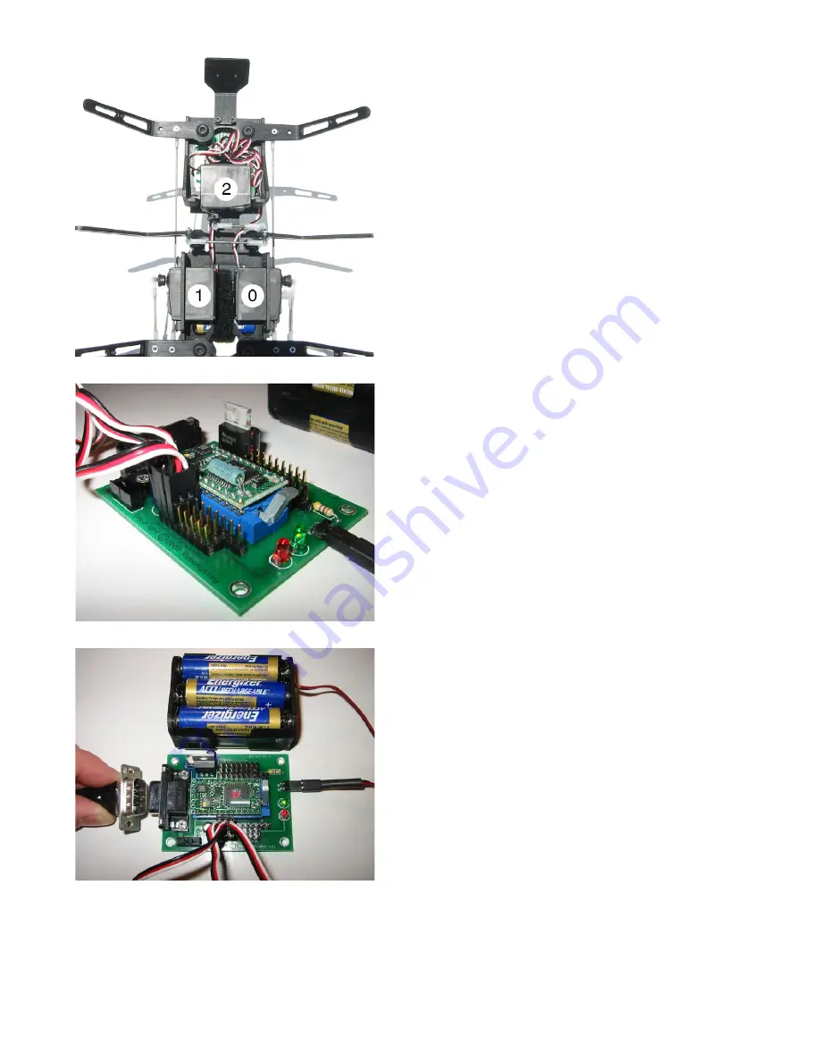
Before attaching the servo arms to the servos, the servos
must be calibrated and centered to ensure accurate po-
sitioning. The easiest way to calibrate your servos is to
connect them to the Robodyssey Advanced Motherboard
with a BasicX or Basic Stamp microcontroller. A RC
receiver and transmitter combination would work just as
well, but is not covered in this documentation.
Insert your microcontroller into the Zero Insertion Force
Socket by lifting the small lever, placing the microcon-
troller in the socket, and then locking the lever in the
down position. Next, connect the three servo wires as
shown in Figure 38.
Connect the servos to the motherboard as follows:
Right Servo: Pin 0 on Motherboard
Left Servo: Pin 1 on Motherboard
Center Servo: Pin 2 on Motherboard
Note that the white wire, which is the signal pin for the
servo, should always be connected to the microcontroller
side of the pins (always toward the
center of the board).
Connect the battery cable to the motherboard as shown
in Figure 39. The green light on the motherboard will
turn on when the batteries are connected properly. If the
green light does not turn on, do not proceed with the fol-
lowing steps until the batteries are oriented properly.
Connect the motherboard to your computer using a serial
DB9 cable as shown in Figure 40. Install the BasicX
Development Software (Available on the Roboydssey
CD, or on http://www.basicx.com), or the Basic Stamp
Development Software (Available on the Robodyssey
CD, or on http://www.parallaxinc.com).
We can now program the microcontroller to center
our three servos automatically. For the BasicX, use
the code shown below in Figure 41, and for the Basic
Stamp, use the code shown in Figure 42. The code
may also be found on the Robodyssey Development
Software CD, or under the “Resources” section of http:
//www.robodyssey.com.
Once you’re ready to go, turn on the motherboard, down-
load the servo centering routine, execute the routine, and
then turn off and disconnect the motherboard from the
servos.
Figure 38
Figure 39
Figure 40


