8
plied with the chimney hood.
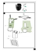
IN THE EXTRACTION MODE:
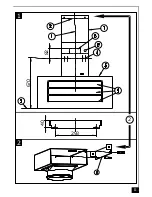
a. Place the anti-backflow flats
item 8
over the round outlet
item 6,
the telescopic duct and connect the
ducting 150mm (6 INS) over the round outlet on top of the canopy and secure the connections with
appropriate clamping rings or adhesive tape (
Fig. 6
).
b. Remove the grease filters (see paragraph Maintenance)
Fig. 5
being sure that the connector of the
mains cable is correctly inserted in the socket placed on the sides of the fan. Before fitting the chimney
to the canopy make the electrical connection as described in the section titled ELECTRICAL. When
the electrical connection has been made, test the lights and the fan motor.
c. Each chimney stack consists of two sections. Fit the upper sections (
Fig. 1 - item 7a & b
) first by
expanding the chimneys slightly to allow them to clamp around the bracket item 2 and secure the
chimney stacks to the brackets using the two M4 screws
item 12c
provided. Fit the lower chimney
sections by expanding the chimneys slightly to allow them from the top of the canopy to clamp around
the upper chimney sections.
d. Fit the 3 deflectors
Item 9.
IN THE RECIRCULATION MODE:
a. Fit the recirculation spigot
R
onto the upper chimney wall bracket using the same fixing screws (
Fig.
2 item 2
).
b. Connect the ducting 150mm (6 INS) not provided between motors
item 6
and the recirculation spigot
and secure the connections with appropriate clamping rings or adhesive tape.
c. Remove the grease filters (see paragraph Maintenance)
Fig. 5
being sure that the connector of the
feeding cable is correctly inserted in the socket placed on the side of the fan. Before fitting the chimney
to the canopy make the electrical connection as described in the section titled ELECTRICAL. When
the electrical connection has been made, test the lights and the fan motor.
d. Insert the charcoal filter into the base of the motor housing and secure the filter with two metal secur
-
ing straps
item A
as illustrated in
Fig. 4
.
e. Each chimney stack consists of two sections. Fit the upper sections (
Fig. 1 - item 7a & b
) first by
expand-ing the chimneys slightly to allow them to clamp around the bracket item 2 and secure the
chimney stacks to the brackets using the two M4 screws
item 12c
provided. Fit the lower chimney
sections by expanding the chimneys slightly to allow them from the top of the canopy to clamp around
the upper chimney sections.
f. Fit the 3 deflectors
Item 9.
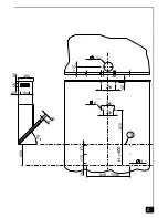
IN THE REMOTE MOTOR MODE AND WITHOUT CHIMNEY:
Note:
The
Fig. 7 & 8
correspond to the versions without Motor and without chimney (SMC or WMC).
GB
Summary of Contents for Lido 2 Murale
Page 14: ......
Page 18: ...8 175 8 175 8 8 9 898 1098 409 12 27 8 4 848 1048 405 A A...
Page 19: ...B...
Page 20: ...45 Composants Components Bauelemente Componenti Componentes Onderdelen 2 R 8 4 6 5 7 9...
Page 21: ...285 40 164 50 56 4 0 4 5 6 400 170 113 6 260 40 293 35 175 175 3 848 1048 670 200 3 H 400...
Page 22: ...359 285 40 164 50 56 4 0 122 6 4 5 473 752 mini maxi 1484 1205 898 1098 438 475 723 150 400 35...
Page 23: ...2 2 1 82 670 293 40...
Page 24: ...3 4 10 10 30 1070 260 4 A...
Page 25: ...A11 5 6 6 R 7a 7b...
Page 27: ...400 6 301 5 35 175 175 3 8 4 8 8 4 1 1 397 251 5 340 97 184 DESSOUS HOTTE PLAN TRAVAIL 41 5...
Page 28: ...4 VIZIO 3 900 SMC 475 4 5 6 473 898 470 285 175 88 42 359 4 0 438 400...
Page 29: ...VIZIO 3 1100 SMC 473 1098 438 475 175 359 6 4 5 285 42 88 470 4 0 400...
Page 30: ...7 397 400 301 5 251 5...
Page 31: ...8 4 10 10 301 5 25 5 1 4...
Page 34: ...A20 Beleuchtung Lighting Eclairage Luci Luz Verlichting LEDS 2 x 7 W Fig 9 Fig 10 1 2 1 1 2 2...
Page 35: ...A21 LEDS 2 x 7 W...


