background image

GB

markings identifying the terminals in your plug, proceed as follows.

- The wire which is coloured green and yellow must be connected to the terminal in the plug which is

marked with the letter 

or by the earth symbol or coloured green or green and yellow.

- The wire which is coloured blue must be connected to the terminal which is marked with the letter 

or

coloured black.

- The wire which is coloured brown must be connected to the terminal which is marked with the letter 

or

coloured red.

ATTENTION    


 E


-


 T  


faulty hanging due to the drilling and the setting up of plugs.

GB

1)

raw a vertical line onto the wall from the centre of the cooking appliance up to the ceilling, using a

spirit level and a marker pen as illustrated in 

Fig. 1 - item 1

. This is to ensure the correct alignment

of the chimney hood.

2) Place the brackets 

item 2

 on the wall about 1 or 2 mm from the ceiling or from the upper limit, aligning

its centre  on the vertical line.  ark the two eyelet holes of the bracket onto the wall.  rill the holes

for the  xing bracket using an   mm masonry bit. Fix the chimney bracket 

item 2

 using the 4.5 x 50

mm screws and rawl plugs supplied.

3)

ark a point on the vertical line at a distance from the cooking appliances of:

d = 

1102 mm

 ( easurement without splashback).

d   height of the splashback (

719 mm

) + 

402 mm

 ( easurement with splashback).

The distance H is the minimum height in mm from the cooking appliances to the bottom edge item 3 of 

the front panel of the hood.  raw a horizontal line through the vertical as illustrated in 

Fig. 1.

Splashback (optional):  hen a splashback is to be  tted, the distance between the hood and the cook

-

ing appliances will be determined by the height of the splashback 

item B

 and whether or not there 

is a raised back on the worktop.  The splashback is to be installed before installing the canopy.  If 

the splashback is to be  xed to the wall using both the top and bottom  xing holes, Care must be 

taken to ensure that the splashback is  tted at the correct height before  xing the base units or at 

least the worktop covering them.  As this is a complex operation, it should only be undertaken by 

the technician installing the kitchen units or by a competent person who knows the  nal dimensions 

of the units.

   ark the hole centres for the canopy  xing brackets 

item 4

 at 

item B

 mm as illustrated in 

Fig. 3

rill the 4 holes for the  xing brackets using an   mm masonry bit. Fix the wall brackets 

item 4

 using 

the 4.5 x 45 mm screws and rawl plugs supplied.

4) Hook the canopy 

item 5

 onto the wall brackets 

item 4

 as illustrated in 

Fig. 3

. To ensure the cooker

hood is aligned correctly ad ust the screws on the top of the canopy as illustrated in 

Fig. 3

      To remove the 2 parts blocking the body of the hood for transport (


).

  hen the hood is aligned correctly mark the hole centre on the wall for the security  xing screw 

item8

, which is located in the right hand bracket on the top of the canopy. Unhook the canopy from 

the wall and drill the hole for the security  xing screw. Hook the canopy onto the wall and  x the No 

4,5 x 50mm headed screw and rawl plug to secure the canopy to the wall.

5)

ucting:

The hood is more effective when used in the extraction mode (ducted to the outside).  hen the cooker 

hood is ducted to the outside, charcoal  lters are not required.The ducting used must be 150 mm (6 

INS), rigid circular pipe and must be manufactured from  re retardant material, produced to BS.4 6 

or  IN 4102-B1.  herever possible use rigid circular pipe which has a smooth interior, rather than 

the expanding concertina type ducting.

aximum length of ducting run:

-   4 metres with 1 x  0  bend.
-   3 metres with 2 x  0  bends.
 -   2 metres with 3 x  0  bends.

Summary of Contents for Escale Murale

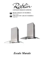
Page 1: ...Escale Murale Mode d emploi et installation Hotte de Cuisine Instructions for use and installation Cooker Hood GB FR...

Page 2: ...POSE DE L APPAREIL FONCTIONNEMENT CONSEILS D UTILISATIONS ENTRETIEN GARANTIE ET SERVICE APR S VENTE REMARQUES GB CONTENTS ELECTRICAL WIRING INSTALLATION ADVICE FITTING THE APPLIANCE OPERATION USEFUL H...

Page 3: ...n aucun cas tre raccord e un conduit de ventilation m canique contr l e V C Lorsqu on vacue l air vici dans un conduit d vacuation veiller ce que celui ci ne soit pas d exploit v hiculer des gaz ou fu...

Page 4: ...s bloquant le corps de la hotte pour le transport Fig 8 Apr s avoir effectu tous les r glages d alignement de l ensemble de la hotte verrouiller celle ci par une vis de xation positive Rep 8 a n de ga...

Page 5: ...s qu moteur teint Affiche 24 et le point en bas droite cli gnote tandis que le moteur est en service Une fois la proc dure termin e la signalisa tion visualis e en pr c dence s teint FF signale la n c...

Page 6: ...ici bserver les prescriptions r glementaires locales concernant l vacuation de l air vici Avant toute intervention sur l appareil mettre l interrupteur d allumage des lampes en position teinte N 7 GAR...

Page 7: ...s et lectroniques Veuillez agir selon les r gles locales et ne pas eter vos produits usag s avec les d chets domestiques usuels eter correctement votre produit usag aidera pr venir les cons quences n...

Page 8: ...d ensure that there is an adequate supply of fresh air to the room Ensure the kitchen is tted with an airbrick which should have a cross sectional measurement equivalent to the diameter of the ducting...

Page 9: ...there is a raised back on the worktop The splashback is to be installed before installing the canopy If the splashback is to be xed to the wall using both the top and bottom xing holes Care must be t...

Page 10: ...expanding the chimneys slightly to allow them from the top of the canopy to clamp around the upper chimney sections IN THE RECIRCULATI N E a Fit the recirculation spigot R onto the upper chimney wall...

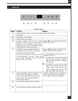
Page 11: ...ns are only visible when the motor is turned off Displays 24 and the bottom right hand spot flashes while the motor is turned on On completing the procedure the previous indicator is turned off FF ind...

Page 12: ...month or more frequently if the hood is used for more than 3 hours per day T Remove the metal grease lters one at a time by releasing the catches on the lters the lters can now be removed The metal g...

Page 13: ...ting from transportation improper use or neglect the replacement of any light bulbs or lters or removable parts of glass or plastic These items are considered to be consumable under the terms of this...

Page 14: ...nection Unit to BS 1363 Part 4 fitted with a 3 Amp fuse is a recommendedmains supply connectionaccessoryto ensure compliance with the Safety Requirements applicable to fixed wiring instructions The wi...

Page 15: ...SS W P WHITE PINK BLANC ROSE WEISS ROSA Y YELLOW JAUNE GELB Brown Blue M N L1 F Blue Brown M 230 W L2 L2 MULTI FLACH KABEL LIMANDE COMMANDE FLAT CABLE FERNBEDIENUNG RECEPTEUR INFRAROUGE REMOTE CONTROL...

Page 16: ...A3 OPTION OPTIONAL OPTIONAL OPZIONALE OPCIONAL OPTIE 6406126 Cr dence Splaschback R ckwand Fondale Credencia Rugwandpaneel...

Page 17: ...A4 700 421 DESSOUS HOTTE au centre PLAN TRAVAIL 170 113 6 260 40 293 200...

Page 18: ...A5 291 164 40 50 56 527 128 898 459 mini 1154 maxi 784 359 20 433 38 54 150 mini 650 35 506 ESCALE Murale INOX...

Page 19: ...A6 291 164 40 50 56 527 128 898 459 mini 1154 maxi 784 359 20 433 43 59 150 mini 650 35 506 ESCALE Murale VERRE...

Page 20: ...A7...

Page 21: ...A8 2 2 1 85 421 293 40 700...

Page 22: ...A9 3 4 10 10 30 1102 260 4 A...

Page 23: ...A10 5 6 6 R 7b 7a...

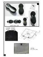
Page 24: ...A11 ACCESSOIRES ACCESSORI ACCESSORIES ACCESORIA ZUBEH RE ACCESSOIRES 7 2 LR03 AAA 1 5V 1 3 13MC092 323 x 262 x 9 mm...

Page 25: ...rie Numero de serie Serienummer Mod le Model Modell Modello Modelo Model Plaque Signal tique de la hotte Rating plate of the cookerhood Typenschild im Inneren der Dunstesse Etichetta all interno della...

Page 26: ...A13 Composants Components Bauelemente Componenti Componentes Onderdelen 2 4 6 5 8 R B 7...

Page 27: ...A14 Halogen Beleuchtung Halogen Lighting Eclairage halog ne Alogene Luci Al genas Luz Halogeen Verlichting 2 x 20 W 12 V G4 12V 20W...

Page 28: ...A15 8...

Page 29: ...25 Rue des Rosiers Sainte C cile B P 60056 50800 VILLEDIEU LES PO LES France T l 02 33 91 26 50 Fax 02 33 51 54 79 e mail com france roblin fr For outside France Tel 33 0 2 33 91 26 57 Fax 33 0 2 33 5...

Reviews: