6
GB
Telescopic CONFORT PRO Motor
The installation of the built-in telescopic DECLIC can be carried out in 2 different ways:
•
Either while integrating the motor in the hood or in the kitchen furniture.
•
Either while separating the motor, to be placed at a distance, in order to be more comfortable improving
noise level
Telescopic Remote MISTRAL 800 external motor
The Mistral 800 external motor is installed with the built-in DECLIC telescopic extractor in the kitchen
furniture, or remotely at a distance fitted on an outside wall.
A - INSTALLATION WITH THE CONFORT PRO MOTOR FIXED INTO THE BUILT-IN TELESCOPIC
EXTRACTOR
1.
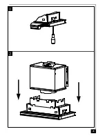
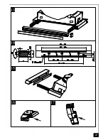
Turn the screws anticlockwise to loosen the 2 fixing clips on the Declic (fig 1).
2.
Position the Confort motor inlet above the Declic and lower into position (fig 2).
3.
Fix the Declic motor assembly to the Confort with the 2 screws (fig 3).
4.
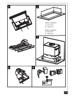
Insert the 4 shock absorbers into the holes in the back of the Confort motor (fig 4).
5.
The Declic is supplied with a 10mm and 20mm spacer to fill the gap between the wall and the rear
of the extractor. To fit the spacer unscrew the screws located between the halogen lights and remove
the front light housing in order to access (fig.5).
6.
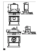
Cut the require aperture in the base of the kitchen cabinet as indicated (fig. 6).
7.
Insert the telescopic extractor in the aperture in the kitchen cabinet and turning the screws clockwise
secure the assembly to the kitchen cabinet (fig 1).
8.
We recommend that the CONFORT PRO motor be secured to the back of the kitchen cabinet,
which will allow access via the cabinet door (fig 7).
9.
Insert the grommets into the screw holes (fig 8).
10. Connect the ducting onto the round outlet on the top of the motor assembly.
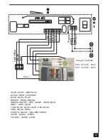
11. Connect both appliances together (fig 9) and connect them to the mains supply (See ELECTRICAL
WIRING chapter).
CAUTION : If the kitchen cabinet does not have a door you must execute points 10 and 11 before
point 7.
•
RECIRCULATION
In the recirculation mode (with the optional activated charcoal filter fitted) the contaminated air enters the
hood through the grease filter and through the purifying activated charcoal filters and back out into the
kitchen through a grille in the front of the kitchen cabinet (fig. 10).
Before the charcoal filter can be fitted it is necessary to fix the propeller shaped bracket over the outlet in
the body of the canopy using the 3 No M4 x 6 screws provided and then the activated charcoal cartridge
can be fitted (fig 11).
B - REMOTE INSTALLATION OF THE DECLIC WITH CONFORT PRO OR MISTRAL 800 MOTOR
See the specific instruction booklet supplied when fitting the remote controlled Confort or Mistral 800 motor
at a distance from the Declic extractor hood.
1.
Turn the screws anticlockwise to loosen the 2 fixing clips on the Declic (fig 1).
2.
The Declic is supplied with a 10mm and 20mm spacer to fill the gap between the wall and the rear of
the extractor. To fit the spacer unscrew the screws located between the halogen lights and remove the
front light housing in order to access (fig.5).
3.
Cut the require aperture in the base of the kitchen cabinet as indicated (fig. 6).
4.
Insert the telescopic extractor in the aperture in the kitchen cabinet and turning the screws clockwise
secure the assembly to the kitchen cabinet (fig 1).
Summary of Contents for DECLIC 609
Page 2: ...DECLIC 609 610 Composants Components Bauelemente Componenti Componentes Onderdelen...
Page 3: ...DECLIC 909 910 Composants Components Bauelemente Componenti Componentes Onderdelen...
Page 13: ...25 2 1...
Page 14: ...26 3 4...
Page 15: ...27 8 5 DECLIC 609 610 A 514 mm B 255 mm DECLIC 909 910 A 814 mm B 255 mm A B 9 6 7...
Page 16: ...28 11 10 12...
Page 17: ...29 16 13 14 17 15...
Page 18: ...30...
Page 22: ...34 A B C D E F F...
Page 23: ...35 G H I J K L...

