background image


16 

Calibration of the scale on the parallel 

fence

 (Fig.23-25)


Each time a new sawblade is fitted the parallel fence scale has to be calibrated to the new sawblade. 

By cutting a sample and measuring its exact length, the scale can be adjusted so that the exact 
measure corresponds with the front side of the fence. 

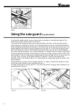
After the screw (1) has been loosened the scale can be adjusted. To avoid the fence contacting the 

sawblade while it is revolving, the stop ring (2) has to be adjusted. Slide the fence to about 10 mm 
from the sawblade. Now slide the stop ring (2) across the round guide bar (3) until it comes up against 
the casting of the fence. Tighten the lock screw on the stop ring.  

For a digital reading: Move the parallel fence against the saw blade, and then simultaneously press 

the “F” and “SET” buttons. The value on the digital reading jumps to “0”. 

Then shift the locking ring (fig. 25.3) onto the saw guide (2) until the cutting width is limited to 2 mm.  
This prevents inadvertent contact with the saw blade. 
If the size display is not correct when the digital display is read, check the distance between the 

sensor (Fig. 23.2) and the digital measuring tape (Fig. 23.1). This may be max 0.2 mm. If necessary, 
adjust this with the adjusting bolts (fig. 23.3). 


Cutting with mitre fence

 (Fig.24)


The nut for receiving the wood clamp shaft (1) is set from the factory and must not be moved. The set 

angle can be read at the rear of the large angle bracket (4). The angle is changed by unloading the 
shaft (1) and releasing the clamping lever (2). The stop profile (5) itself can be moved by releasing the 
2 clamping levers (3). 

Summary of Contents for M500 EL

Page 1: ...hanging main sawblade Fig 9 10 Use and adjustment of the riving knife Fig 10 11 11 Lower sawblade cover 12 Adjusting the main sawblade 12 Adjusting the main sawblade M500EL 13 Blocking the sliding tab...

Page 2: ...fety devices are fitted to the machine and that the machine is connected to a dust extraction system Keep dust levels down with good housekeeping Keep the work area clean so you do not resuspend dust...

Page 3: ...cumulation of potential energy of the elastic elements springs elements of the machine or machined pieces Risk of crushing Risk of cuts Risk of gasping wrapping Risk of electric shock or pinching Ejec...

Page 4: ...rotective caps and means provided on the machine must be used This also applies to the dust emission and means that the machine must be connected to a dust extraction system whose air flow rate measur...

Page 5: ...de is rotating Risks for the machine tools and safety equipment when setting the parallel fence with rotating saw blade SOUND REDUCTION The type and condition of the saw blade is important to keep the...

Page 6: ...6 General dimensions...

Page 7: ...lting of saw aggregate Preparation groove cutter Mitre fence on sliding table Extra support table with rip fence Eccentric clamp Digital read out of tilt of the saw aggregate Digital read out of heigh...

Page 8: ...manner The machine must be levelled in both directions There are 6 adjusting bolts on the machine see fig 2 Electrical connection Fig 3 The electrical connection must be carried out by a qualified el...

Page 9: ...done in the factory Simply put the table onto the frame with the two lateral adjustment bolts 1 into the two lugs of the frame Be sure that the girder rests well in the height adjustment bolts Now pla...

Page 10: ...0 seconds as soon as the machine is shut off ATTENTION When the machine access door is open the saw blade cover is open or one of the emergency stops is pushed in the machine cannot be started All fus...

Page 11: ...e panel saw must have two additional holes in the sawblade body to prevent the sawblade from loosening when the rotation of the saw spindle is stopped by the brake on the motor The two little bolts in...

Page 12: ...usted vertically with the handwheel 1 and the handle 2 The height adjustment of the scoring saw is done with the adjusting knob 5 fig 12A Lock the setting with the serrated nut 4 fig 12A The desired c...

Page 13: ...your direction and turn to the right to liberate the table Pull the sliding table till end the table will be blocked automatically when arriving in the exact position Continue this way to start workin...

Page 14: ...ut fence on the cross cut table place the fence with the right hinge pin 1 in the fastening hole on the front of the table fig 18B Now place the clamping screw 2 Slide the fence backwards until the st...

Page 15: ...handle 1 down to lock the fence in place When cutting small workpieces with the saw unit inclined at 45 the fence should be used in the low position Simply unlock the eccentric clamping handle 4 slid...

Page 16: ...ing Move the parallel fence against the saw blade and then simultaneously press the F and SET buttons The value on the digital reading jumps to 0 Then shift the locking ring fig 25 3 onto the saw guid...

Page 17: ...ork table The saw cover will automatically raise when entering workpieces up to a certain thickness For workpieces where a larger cutting height is required grasp the saw blade on the handle 4 pull th...

Page 18: ...the belt regularly and change if necessary order number NXPA800 Only use Robland replacement parts Adjusting the brake of the saw motor If the run down time of the saw motor exceeds 10 seconds then t...

Page 19: ...are dust tight and require no lubrication Remove any resin deposits on the machine and regularly lubricate the steel axle of the parallel fence Caution when using solvents be very careful about the ri...

Page 20: ...ically after shut off and cooling down period overload is not set on automatic reset or the overload is faulty If you cannot solve the problem yourself or you do not find your problem in this list ple...

Reviews: