


- 23 -
Fig. 5-14a
Step
Parts to remove
Remarks and procedures
Fasteners
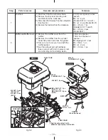
19
Rocker cover
(1) Remove the rocker cover from the
cylinder head.
(2) Remove the gasket (rocker cover).
10 mm box spanner
M6 × 12mm : 4 pcs.
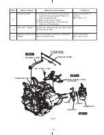
20
Rocker arm
Remove the pin (rocker arm) and the rocker
arm from the cylinder head at the compression
top dead center. (See Fig. 5-14b)
Fig. 5-13
ROCKER ARM
(EXHAUST VALVE SIDE)
ROCKER ARM (INTAKE VALVE SIDE)
PIN
(ROCKER ARM)
ROCKER ARM
(EXHAUST
VALVE SIDE)
PIN
(ROCKER ARM)
CLOSE-UP A
A
ROCKER ARM
(INTAKE VALVE SIDE)
ROCKER COVER
GASKET (ROCKER COVER)
M6 x 12 BOLT : 4 pcs.
STEP 20
STEP 19
Punch marks
The position of compression top dead center
Fig. 5-14b
Summary of Contents for EX13
Page 1: ...SERVICE MANUAL EX13 17 21 27 SP170 SP210 ENGINES Models PUB ES1934 Rev 06 09 ...
Page 3: ......
Page 87: ......
Page 88: ...PRINTED IN THE USA ...


