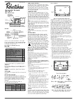


Figure 5. Typical wiring diagram for two transformer
heat pump systems with safety circuits in BOTH
systems
Figure 6. Typical wiring diagram for single
transformer multi-stage systems
Heat Pump Terminal Outputs
Refer to equipment manufacturer’s instructions for specific
system wiring information. You can configure the thermostat
for use with the following heat pump system types: HEAT
PUMP TYPE 1 1. Single stage compressor system; gas or
electric backup. This thermostat is designed to operate a
single-transformer system. If you have a two-transformer
system, cut and tape off one transformer. If transformer
safety circuits are in only one of the systems, remove the
transformer of the system with NO safety circuits. If
required, replace remaining transformer with a 75VA Class II
transformer. After disconnecting one transformer, the two
commons must be jumpered together.
Use the terminal output information below to help you wire
the thermostat properly for your heat pump system. After
wiring, see CONFIGURATION section for proper thermostat
configuration.
CHECK THERMOSTAT OPERATION
Note:
To prevent static discharge problems, touch side of
thermostat to release static build-up before touching
any keys.
If at any time during testing your system does not
operate properly, contact a qualified service person.
Fan Operation
If your system does not have a G terminal connection, skip
to
Heating System.
1. Turn on power to system.
2. Move Fan switch to ON position. The blower should
begin to operate.
3. Move Fan switch to AUTO position. The blower should
stop immediately
Heating System
1. Move System switch to Heat mode. If the auxiliary
heating system has a standing pilot, be sure to light it.
2. Press to adjust thermostat setting to 1ºF/1°C above room
temperature. The heating system should begin to oper-
ate. The display should show STG1. However, if the set-
point temperature display is flashing, the compressor
lockout feature is operating (see Configuration Menu,
item 5).
3. Adjust temperature setting to 3ºF/3°C above room tem-
perature. If your system configuration is set at MS2, HP2
or HP1, the auxiliary heat system should begin to operate
and the display should show STG1+2.
4. Press to adjust the thermostat below room temperature.
The heating system should stop operating.
Emergency System
EMER bypasses the heat pump to use the heat source
wired to terminal E on the thermostat. EMER is typically
used when compressor operation is not desired, or you
prefer back-up heat only.
1. Press System switch to select Heat mode. then press
EMER key. EMER will show on the display.
2. Press to adjust thermostat setting above room tempera-
ture. The auxiliary heating system will begin to operate.
The display will show STG1 EMER to indicate that the
auxiliary system is operating.
3. Adjust temperature setting to 2ºF/2°C above room
temperature. The auxiliary heat system should begin
to operate and the display should show STG1+2.
4. Press to adjust the thermostat below room temperature.
The auxiliary heating system should stop operating.
Cooling System
1. Move System switch to select the Cool mode.
2. Press to adjust thermostat setting below room tempera-
ture. The blower should come on immediately on high
speed, followed by cold air circulation. The display
should show STG1.
3. Press to adjust the temperature setting above room tem-
perature. The cooling system should stop operating.
CONFIGURATION MENU
The configuration menu allows you to set certain thermostat
operating characteristics to your system or personal
requirements. Set System switch to OFF, then simultane-
ously press up and down keys to enter configuration menu.
The display will show the first item in the configuration
menu. The configuration menu table summarizes the con-
figuration options. An explanation of each option follows.
Press F key to change to the next menu item. To exit the
menu and return to the program operation, press Hold/Run
key. If no keys are pressed within fifteen seconds, the
thermostat will revert to normal operation.
1) Single Stage, Multi-stage or Heat Pump System
Configuration
This control can be configured for Heat Pump or two
stage heat/one stage cool multi-stage operation. The
display indicates MS 2 (default for multi-stage mode) in
the display. The multi-stage configuration can be toggled
to SS1, or HP1 by pressing the up or down key. In
multi-stage configuration, EMER mode is not used.
In this model, the HP2 is not used.
2) Fast or slow cycle selection (one stage)
3) Select backlight function OFF or on
4) Fast or slow cycle selection (two stage)
5) Select °F or °C readout. When you change this parame-
ter, the programming returns to default. You have to set
the program again.
6) Selects time format to display in 12-hour or 24-hour
clock
7) Select compressor lockout (COMP OFF or ON)
Selecting COMP ON will cause the thermostat to wait 4
minutes before turning on the compressor if the heating
and cooling system loses power. It will also wait 5 min-
utes minimum between cooling and heating cycles. This
is intended to help protect the compressor from short
cycling. Some newer compressors already have a time
delay built in and do not require this feature. Your com-
pressor manufacturer can tell you if the lockout feature
is already present in their system. When the thermostat
compressor time delay occurs it will flash the setpoint
for about four minutes.
8) Select 1 to reset to factory defaults.
Setting Time And Day
Remove the mylar label covering the LCD
display window before operating thermo-
stat.
• Initial display after power-up. The tem-
perature will update after a few seconds.
• During Time and Day Setting mode, the
temperature and program display will go
blank.
• Press and hold HOUR to rapid advance
to the current hour. Tap to advance one hour at a
time. Note the AM/PM indicator, as the display will
cycle through 24 hours.
• Press and hold MIN to rapid advance to the current
minute.
• Tap to advance one minute at a time.
• Tap DAY to advance one day at a time.
• When finished press HOLD/RUN to return to normal
mode. After 15 seconds, the thermostat will return to nor-
mal automatically.
Auto Programming
Studies conducted by the Department of Energy
estimate that setting your thermostat back 10ºF
(6°C) for two 8-hour periods during winter can
reduce your fuel bill by as much as much as
33%. Setting your thermostat up 5ºF (3°C) for
two 8-hour periods during summer can reduce
your fuel bill up to 25%.
Your thermostat is capable of holding up to
4 separate programs for each day of the week.
You can program all weekdays, Monday to
Friday, to the same 4 programs as shown in the table,
or each weekday can have a different set of 4 programs.
Similarly weekend programs, (Saturday and Sunday) can
be the same 4 programs or each weekend day can have
a different set of 4 programs.
Your thermostat is pre-programmed to meet the ENERGY
STAR™ guidelines for energy efficiency. Note that it is
easier to modify these programs than to program the
thermostat manually.
• Press once. During Auto Programming,
the display will change as shown.
• The thermostat will be programmed for
all 7 days of the week as shown below.
• Refer to
Manual Programming
for entering or changing
the programs.
PROGRAMMING
Before programming or changing programs, use this
Personal Program Schedule to determine which times and
temperature settings will best satisfy both your comfort and
energy saving requirements. Use a pencil so you can revise
yours records each time you change your temperature
settings.
Heating
Cooling
Manual Programming
• Your thermostat can be programmed for weekdays and
weekends. Use Weekday/Weekend Programs to enter
or revise programs to match your Personal Program
Schedule. The same steps are used when entering
programs for the first time or revising programs entered
during Auto Programming.
• Familiarize yourself with Manual Programming, so that
you can easily modify your programs as your comfort
needs change. The example below demonstrates the
Manual Programming method.
NOTE:
1. The program time can be set in 10-minute increments,
and remains the same for both Heat and Cool programs.
2. The program temperature can be set in increments of 1ºF
(1ºC).
3. The heat setpoint cannot be set higher than the cool
setpoint, and the cool setpoint cannot be set lower than
the heat setpoint.
Temperature in Fº (Cº)
Program Number
Time
Heat
Cool
1
6:00 am
68ºF(20ºC)
78ºF(26ºC)
2
8:00 am
60ºF(16ºC)
85ºF(29ºC)
3
4:00 pm
68ºF(20ºC)
78ºF(26ºC)
4
10:00 pm
60ºF(16ºC)
85ºF(28ºC)
DAY
Program 1
Program 2
Program 3
Program 4
Mon
Time
Time
Time
Time
Temp
Temp
Temp
Temp
Tue
Time
Time
Time
Time
Temp
Temp
Temp
Temp
Wed
Time
Time
Time
Time
Temp
Temp
Temp
Temp
Thu
Time
Time
Time
Time
Temp
Temp
Temp
Temp
Fri
Time
Time
Time
Time
Temp
Temp
Temp
Temp
Sat
Time
Time
Time
Time
Temp
Temp
Temp
Temp
Sun
Time
Time
Time
Time
Temp
Temp
Temp
Temp
THERMOSTAT TERMINALS (HEAT PUMP)
SYSTEM
Heat Pump 1
L
Malfunction
C*
24 Volt (common)
R
24 Volt Emergency (hot)
E/W1
Emergency Mode 1st stage
W2
HP 1 and Emergency 2nd stage
Y1
Heat and Cool mode 1st stage (compressor)
G
Blower/Fan Energized on call for Heat and Cool
Set GAS/ELEC switch for Emergency mode
O
Energized in Cool Mode
B
Energized in Heat Emergency mode
352-00021-004 Rev B 5/08
INSTALLER/CONFIGURATION MENU
Step
Press
Button
Displayed
(Factory
Default)
Press
down key
to select
Comments
1
F
MS 2
SS1, HP2,
HP1
Selects Single stage,
Multi-stage or Heat
Pump (Single stage or
2-stage) System
Configuration
2
F
(DIFF)2
1,3
DIFF (one stage)
3
F
(BLIT)on
off
BackLight
4
F
(SP2)2
1,3
DIFF (Two Stage)
5
F
(TEMP)F
C
Selects temperature
display °F or °C
6
F
HOUR(12)
24
Selects time format
display 12 hours or
24 hours
7
F
COMP(OFF)
ON
Selects Compressor
Lockout OFF or ON
8
F
FACT(0)
1,2
Select 1 to reset to
factory defaults