


FEATURES
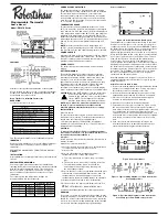
Structure of thermostat and explanation of the keypads
We are pleased you have selected our wall thermostat. Our
products are manufactured to high quality standards and
are designed for years of service.
Read This Before Installing Thermostat
OPERATION
YOUR THERMOSTAT FUNCTIONS WITH
This Thermostat will NOT control 110/220 Volt systems.
IMPORTANT
Read the entire installation section of this Owner’s Manual
thoroughly before you begin to install or operate your
thermostat.
REMOVE THE MYLAR LABEL FROM THE LCD DISPLAY
WINDOW.
INSTALLATION
All programming is normally performed at your thermostats
location.
ARMCHAIR PROGRAMMING
You can program your thermostat before installation by
inserting the batteries and following the instructions starting
with the installer/configuration menu. This can be done
while you relax in your favorite chair and is a very good
way to familiarize yourself with all the functions of your
thermostat.
The following time and temperature settings are
pre-programmed into the thermostat:
COMPRESSOR PROTECTION
The thermostat provides a 4-minute delay after shutting
off the heating or cooling system before it can be restarted.
This feature will prevent damage to your compressor
caused by rapid cycling. Note that this delay also applies
to the heating system control. It does not provide a delay
when there are power outages. You can select the function
on or off at the configuration.
TEMPERATURE RANGE
This thermostat can be programmed between 45ºF and
95ºF (7ºC and 35ºC). However, it will display room tempera-
tures from 30ºF to 99ºF (0ºC and 37ºC). HI will be displayed
if the temperature is higher than 99ºF (37ºC), and LO will be
displayed if the temperature is lower than 30ºF (0ºC).This
thermostat will automatically shut down in Heat mode if the
temperature rises above 95ºF (35ºC), and automatically shut
down in Cool mode if the temperature drops below 45ºF
(7ºC).
NOTE:
If the thermostat measures a temperature over
99ºF(37º), HI will be displayed on the LCD. If the tempera-
ture is below 32ºF(0º). and LO will be displayed on the LCD.
POWER FAILURE
Whenever the main power is interrupted or fails, the backup
battery power will maintain the current time. This thermo-
stat also contains permanent memory that will retain your
program setting through power outages.
POWER SUPPLY
The thermostat is powered by 24 VAC and has battery
backup.
BATTERY WARNING
Fresh alkaline batteries should provide about one year
of service. When the batteries become weak, BATT will
alternate on the display with the current time. When this
message occurs, install 2 new AA batteries. You have
approximately 1 minute to change the batteries and keep
the thermostat’s clock and program settings. Once the
batteries have become too weak to ensure proper
operation, your system will be turned off, and the display
will be cleared except for BATT flashing on the LCD display.
CAUTION:
Once the BATT display occurs, the thermostat
is shut down, and your system will no longer
operate. In this condition, there is no temperature
control. NOTE: The backlight will not function
when the thermostat is in low battery condition.
NOTE: If you plan to be away from the premises over
30 days, we recommend that you replace the old
batteries with new alkaline batteries prior to leaving.
INSTALLATION
What You Need:
This thermostat includes two #8 slotted screws and two
wall anchors for mounting. To install your thermostat, you
should have the following tools and materials.
• Slotted screwdriver(s) • Small Phillips screwdriver •
Hammer • Electric drill and 3/16” bit • Two1.5V (AA) size
alkaline batteries (included)
CAUTION:
To prevent electrical shock and/or equipment damage,
disconnect electric power to system at main fuse or cir-
cuit breaker box until installation is
complete.
Before removing wires from old thermostat, label each wire
with the terminal
designation it was removed from.
1. Shut off electricity at the main fuse box until installation
is complete. Ensure that electrical power is
disconnected.
2. Remove old thermostat: A standard heat/cool
thermostat consists of three basic parts:
a. The cover, which may be either a snap-on or hinge
type.
b. The base, which is removed by loosening all screws.
c. The switching subbase, which is removed by
unscrewing the mounting screws that hold it on
the wall or adapter plate.
3. Remove the front cover of the old thermostat. With wires
still attached, remove wallplate from the wall. If the old
thermostat has a wall mounting plate, remove the
thermostat and the wall mounting plate as an assembly.
4. Identify each wire attached to the old thermostat.
5. Disconnect the wires from the old thermostat one at a
time.
DO NOT LET WIRES FALL BACK INTO THE WALL.
6. Install new thermostat using the following procedures.
WARNING
Do not use on circuits exceeding specified voltage. Higher
voltage will damage control and could cause a shock or fire
hazard. Do not short out terminals on gas valve or primary
control to test. Incorrect wiring will damage thermostat and
could cause personal injury and/or property damage.
Selector Switches
Figure 1. Electric/Gas Switch (Fan Option)
This thermostat is configured from the factory to operate a
heat/cool, fossil fuel (gas, oil, etc.), forced air system. It is
configured correctly for any system that DOES NOT require
the thermostat to energize the fan on a call for heat. If your
system is an electric heat or heat-pump system that
requires the thermostat to turn on the fan on a call for heat,
locate the ELEC/GAS switch on the back of the thermostat
(see Figure 1) and switch it to the ELEC position. This will
allow the thermostat to energize the fan immediately on
a call for heat. If you are unsure if the heating/cooling
system requires the thermostat to control the fan, contact a
qualified heating and air conditioning service person. When
the thermostat is configured for heat pump, the thermostat
will always power the circulator fan on a call for heat in the
Heat mode. The ELEC/GAS switch must be set to match
the type of auxiliary heat your system uses for proper
operation in the Emergency mode.
All wiring diagrams are for typical systems only. Refer to
equipment manufacturer’s instructions for specific system
wiring information.
Attach Thermostat Base to Wall
1. Remove the packing material from the thermostat. Gently
pull the cover straight off the base. Forcing or prying on
the thermostat will cause damage to the unit.
2. Connect wires beneath terminal screws on base using
appropriate wiring schematic (see Figures. 2 through 6).
3. Place base over hole in wall and mark mounting hole
locations on wall using base as a template.
4. Move base out of the way. Drill mounting holes.
5. Fasten base loosely to wall, as shown in Figure 1, using
two mounting screws. Place a level against bottom of
base, adjust until level, and then tighten screws. (Leveling
is for appearance only and will not affect thermostat
operation.) If you are using existing mounting holes, or if
holes drilled are too large and do not allow you to tighten
base snugly, use plastic screw anchors to secure sub-
base.
6. Push excess wire into wall and plug hole with a fire
resistant material (such as fiberglass insulation) to pre-
vent drafts from affecting thermostat operation.
Figure 2. Thermostat base
Figure 3. Typical wiring diagram for single transformer
heat pump systems
Figure 4. Typical wiring diagram for two transformer
heat pump systems with NO safety circuits
Programmable Thermostat
Owners Manual
Model: RS3210 Series
Description
Heat Pump (No Auxiliary or Emergency Heat)
Yes
Heat Pump (With Auxiliary or Emergency Heat)
Yes
Standard Heat & Cooling Systems
Yes
Two Stage Heat & One Stage Cool
Yes
Standard Heat Only Systems
Yes
Millivolt Heat Only Systems – Floor or Wall Furnaces
Yes
Standard Central Air Conditioning
Yes
Gas or Oil Heat
Yes
Electric Furnace
Yes
Hydronic (Hot Water) Zone Heat-2 Wires
Yes
Hydronic (Hot Water) Zone Heat–3 Wires
No
352-00021-004 Rev B
Temperature in Fº (Cº)
Program Number
Time
Heat
Cool
1
6:00 am
68ºF(20ºC)
78ºF(26ºC)
2
8:00 am
60ºF(16ºC)
85ºF(29ºC)
3
4:00 pm
68ºF(20ºC)
78ºF(26ºC)
4
10:00 pm
60ºF(16ºC)
82ºF(28ºC)