background image

WARNING

Installation must be done by a contractor qualified 
in the installation and service of gas-fired heating 
equipment or your gas supplier.

Improper installation, adjustment, alteration, service 
or maintenance can result in death, injury or 
property damage. Read the Installation, Operation 
and Service Manual thoroughly before installing or 
servicing this equipment.

Installer

Please take the time to read and understand

these instructions prior to any installation.

Installer must give a copy of this manual to the owner.

Owner

Keep this manual in a safe place in order to provide

your service technician with necessary information.

Roberts-Gordon LLC

1250 William Street
P.O. Box 44
Buffalo, New York 14240-0044
Telephone: +1.716.852.4400
Fax: +1.716.852.0854
Toll Free: 800.828.7450

www.robertsgordon.com

© 2018 Roberts-Gordon LLC

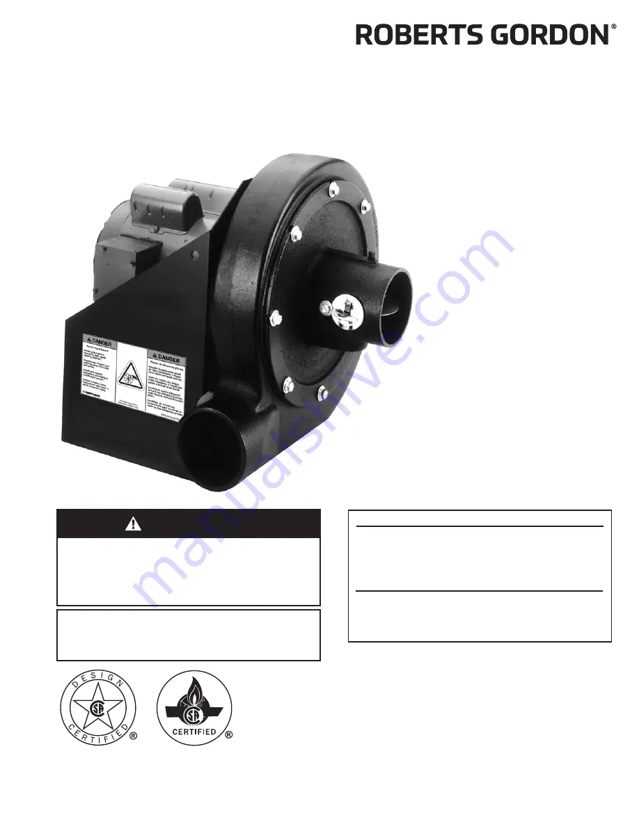
EP-200 Series

Pump

Installation,

Operation &

Service Manual

P/N 127200NA Re

v

. M 3/18

Summary of Contents for EP 201

Page 1: ... this equipment Installer Please take the time to read and understand these instructions prior to any installation Installer must give a copy of this manual to the owner Owner Keep this manual in a safe place in order to provide your service technician with necessary information Roberts Gordon LLC 1250 William Street P O Box 44 Buffalo New York 14240 0044 Telephone 1 716 852 4400 Fax 1 716 852 085...

Page 2: ......

Page 3: ...N 6 Pressure Switch Mounting and Wiring 12 6 1 Pressure Switch Installation 12 SECTION 7 Pump Mounting Instructions 13 7 1 Wall Mounting 13 7 2 Mounting Platform Optional Platform Assembly 14 SECTION 8 Motor Wiring 15 8 1 Impeller Rotation Direction 15 8 2 EP 201 Wiring 15 8 3 EP 203 Wiring 15 SECTION 9 Venting 16 9 1 General Venting Requirements 16 9 2 Venting the Pump 16 9 3 Vent Material Recomm...

Page 4: ......

Page 5: ...gure 5 Motor Shaft Seal Assembly 11 Figure 6 Pressure Switch Mounting Holes 12 Figure 7 Mounted Pressure Switch 12 Figure 8 Pump Pressure Switch Wiring 12 Figure 9 Wall Bracket Assembly 13 Figure 10 Wall Mounting Angle Assembly 13 Figure 11 Wall Mounting 14 Figure 12 Mounting Platform Assembly 14 Figure 13 Side Wall Venting 17 Figure 14 Vertical Venting 18 Figure 15 Condensate Check Valve 18 Figur...

Page 6: ......

Page 7: ... use of work gloves is recommended Do not attempt to operate the pump until all steps of the installation have been accomplished This pump must be applied and operated under the general concepts of reasonable use and installed using best building practices This equipment is not intended for use by persons including children with reduced physical sensory or mental capabilities or lack of experience...

Page 8: ...EP 200 SERIES PUMP INSTALLATION OPERATION AND SERVICE MANUAL 2 of 27 FIGURE 1 Label Placement Description Part Number Severe Injury Label 91012100 Rating Plate Label 91010401 Logo Label 91017200 ...

Page 9: ...ition 2 1 Corrosive Chemicals Roberts Gordon LLC cannot be responsible for ensuring that all appropriate safety measures are undertaken prior to installation this is entirely the responsibility of the installer It is essential that the contractor the sub contractor or the owner identifies the presence of combustible materials corrosive chemicals or halogenated hydrocarbons anywhere in the premises...

Page 10: ...the cartons Lift assembly by gripping metal pump frame Two people are required weight 112 lb 51 kg This pump has been tested prior to packing The impeller was dynamically balanced before assembly and requires care in handling to avoid damage WARNING Cut Pinch Hazard Wear protective gear during installation operation and service Edges are sharp Failure to follow these instructions can result in inj...

Page 11: ...ptions EP 201 Pump Assembly 01312001 EP 203 Pump Assembly 01312002 Pump Scroll Assembly 01394401 Band Clamp 5 13 cm 91901301 Bird Screen 4 10 cm 01365400 Mounting Angle 01365000 Flexible Boot 4 5 11 cm 91412801 Silicone Rubber Ring 91906900 Pump Inlet Assembly 01327400 Pressure Switch 90430600K ...

Page 12: ... Seal 1 91312600 Sleaving 1 91406940 Pump Gaskets 4 93413008 Bolt 1 4 20 x 1 2 1 127200NA EP 200 Series Installation Operation and Service Manual 1 01311700 EP 200 Pump Accessory Kit Includes 1 91901301 Band Clamp 5 13 cm 4 92113900 Hex Nut 6 93413912 Bolt 5 16 18 x 3 4 6 94273914 Bolt 5 16 18 x 7 8 16 95211600 Flat Washer 5 16 28 96411600 Lockwasher 5 16 6 91412801 4 5 Flexible Boot 2 91906900 Si...

Page 13: ...Bolt 1 4 20 x 1 2 1 127200NA EP 200 Series Installation Operation and Service Manual 1 01311700 EP 200 Pump Accessory Kit Includes 1 91901301 Band Clamp 5 13 cm 4 92113900 Hex Nut 6 93413912 Bolt 5 16 18 x 3 4 6 94273914 Bolt 5 16 18 x 7 8 16 95211600 Flat Washer 5 16 28 96411600 Lockwasher 5 16 6 91412801 4 5 Flexible Boot 2 91906900 Silicone Rubber Ring 2 90430600K Pressure Switch Kit Includes 1...

Page 14: ...o National Fire Pro tection Association NFPA 30A latest revision is required An arrow is affixed to the outside of the pump scroll to indicate the direction of rotation of the impeller The standard rotation of the impeller is in the counter clockwise direction Pump discharge orientation and impeller rotation direction is viewed from the rear of the motor as shown on Page 9 Figure 3 Note that the p...

Page 15: ...ends of the mounting screws Make sure the ends of the opposing gasket seg ments interlock to form a complete circular gasket Carefully position the pump scroll against the ver tical mounting plate of the pump frame align and loosely install the 5 16 x 7 8 screws into the cor responding mounting holes in the pump scroll While tightening the screws torque to 132 in lb that secure the pump scroll to ...

Page 16: ... plate assembly as shown The 1 8 NPT plug should face directly up and 1 NPT plug should face directly downward Carefully position top center mounting notch of inlet plate assembly to engage mounting screw positioned previously Install seven remaining 5 16 x 7 8 screws through notches in inlet plate assembly and into corresponding mounting holes in pump scroll Tighten screws torque to 132 in lb to ...

Page 17: ...e motor shaft seal at pre cut score line 2 Wrap shaft seal around motor shaft hub as shown on Page 11 Figure 5 3 Secure shaft seal in position with adhesive strip provided Motor Shaft Seal EP 201 Motor or EP 203 Motor Pump Frame Motor Shaft Hub Impeller Inlet Plate Assembly Pump Scroll Description Part Number EP 201 Motor 90604500 EP 203 Motor 90604501 Motor Shaft Seal 02757500 Pump Scroll 0139440...

Page 18: ...tch to the pump frame Thread the barbed fitting into the threaded hole at the pump inlet Cut the silicone tube to the appropriate length to eliminate the possibility of kinks and securely attach the hose to the pressure switch and the barbed fitting FIGURE 7 Mounted Pressure Switch FIGURE 8 Pump Pressure Switch Wiring Pressure Switch Mounting Holes located on both sides of pump frame Barbed Fittin...

Page 19: ... anchors Select an anchor that will give equal to or greater than 2000 lb ultimate pull out strength For CRVSF Series only a minimum of 18 ceiling clearance in accordance to National Fire Protection Association NFPA 30A latest revision is required FIGURE 9 Wall Bracket Assembly FIGURE 10 Wall Mounting Angle Assembly Mounting Angle Hex Bolt Flat Washer Lockwasher Hex Nut Flat Washer Description Par...

Page 20: ...form Assembly If mounting on an outside wall is not practical it may be mounted on a platform suspended from the ceiling or for noise reduction in an enclosure FIGURE 12 Mounting Platform Assembly Description Part Number Mounting Angle 01365000 Hex Bolt 5 16 x 3 4 93413912 Flat Washer 95211600 Lockwasher 96411600 Hex Nut 92113900 ...

Page 21: ...led by a CORAYVAC Heating Control use Contactor Package 17A P N 10050011 See ROBERTS GORDON CORAYVAC Heating Control Manual P N 10091601NA wiring details Wire the pressure switch per the CORAYVAC Man ual P N 127102NA for CRV models CORAYVAC Classic SF 127302NA for CRVSF models or VAN TAGE CTHN P N 152101NA Installation Operation and Service Manuals 8 3 EP 203 Wiring The EP 203 motor can be wired f...

Page 22: ...ischarge must be arranged as shown on Page 18 Figure 14 Corrosion resistant pipe is required Both horizontal and vertical venting must be sup ported by suitable hangers Vent lengths are allowed as follows 9 3 Vent Material Recommendations Vent recommendations 1 Porcelain coated tubing 4 10 cm O D P N 9141030D 2 Heat treated aluminized tubing 4 10 cm O D P N 91409408 Heat treated aluminized tubing ...

Page 23: ...he discharge line from the pump to the point of discharge Vent terminal opening must extend beyond any combustible overhang Install vent terminal at a height sufficient to prevent blockage by snow Protect building materials from degradation by flue gases Any portion of flue pipe passing through a combustible wall must be dual insulated and an approved thimble must be used FIGURE 13 Side Wall Venti...

Page 24: ...th Seal all discharge pipe joints with high temperature silicone adhesive Vertical venting for CRVSF systems is not recommended FIGURE 14 Vertical Venting FIGURE 15 Condensate Check Valve Description Part Number Tee 4 10 cm 01330203 Drain Cap 4 10 cm 02718851 6 15 cm Bird Screen Optional NOTE Vacuum loss may occur when using vent caps The use of bird screen to cover vent terminations is recommende...

Page 25: ... 100 000 Btu h installed Step 2 Total condensate Determine the total condensate gal h using the follow calculation Total condensate gal h Total Input Btu h 100 000 Btu h x condensate flow gal h Step 3 Choose the condensate neutralization tube Choose the condensate neutralization tube which is closest to and higher than the calculated gal h value Example CORAYVAC system has a total input of 600 000...

Page 26: ... Number Less than 2 Condensate Neutralization Tube 200 01327002 Less than 6 Condensate Neutralization Tube 600 01327003 Less than 10 Condensate Neutralization Tube 1000 01327004 Less than 20 Condensate Neutralization Tube 2000 01327005 Description Part Number Condensate Neutralization Tube 200 01327002 Condensate Neutralization Tube 600 01327003 Condensate Neutralization Tube 1000 01327004 Condens...

Page 27: ...ce the electrical vent ing suspensions and overall pump condition are some of the areas requiring inspection Please see Page 23 Section 10 3 for suggested items to inspect 10 2 To Change the Motor and or the Impeller 1 Diconnect electrical before servicing 2 To remove the motor or impeller the scroll must be opened Remove the eight nuts bolts and insert a knife blade between the scroll halves to c...

Page 28: ...e removed and reinstalled with a drop of thread locking sealant and remain unseated during initial re assembly 7 Slide the impeller onto the motor shaft end Apply a drop of thread locking sealant to the threads of the retainer screw washer assembly Insert the retainer screw into the shaft so that it bottoms on the end of the shaft and hub of the impeller Torque to 30 in lb 8 Seat the two impeller ...

Page 29: ...any gaps in venting to prevent condensate leakage Pump Scroll Impeller and Motor Compressed air or a vacuum cleaner may be used to clean dust and dirt Check for corrosion if any parts have corroded through replace as neces sary Ensure all hex nuts are tight for proper seal Suspension Points Make sure the pump is hanging securely Look for signs of wear on the mounting angles wall mounting points or...

Page 30: ...y 01313800 Impeller 1 2 Bore 01394600 Mounting Angle Assembly 01312102 Pressure Switch Kit 90430600K Inlet Plate Assembly Kit 01327401 Rubber Mounts for Pump Motor 91906100 Flexible Boot Replacement Package 02771000 Pump Scroll 01394401 Description Part Number Description Part Number 4 Plain Coupling 01312700 4 Aluminized 90 Elbow 01335801 6 Plain Coupling 01312706 6 Aluminized 90 Elbow T0100320 4...

Page 31: ...IES 25 of 27 Schedule 40 Damper Nipple 01322000 4 Drain Cap 02718851 4 Coated Cross 0133092D 6 Drain Cap 02718852 5 13 cm Band Clamp 91901301 Condensate Trap 01327001 6 15 cm Band Clamp 91913703 Description Part Number Description Part Number ...

Page 32: ... thermostats etc can be wired into the electrical supply External controls supplied as an optional extra See the heaters Installation Opera tion and Service Manual for details C B G A E D F dia Pump Specifications Model EP 201 EP 203 Horsepower Hp 3 4 3 4 Phase Ø 1 3 Hertz Hz 60 60 Voltage V 115 208 230 208 230 460 Full Load Amp A 8 0 4 42 4 0 2 5 2 26 1 13 R P M 3500 3475 Motor Frame 56 56 Motor ...

Page 33: ... original purchase date and required annual maintenance history The data plate and or serial number are removed defaced modified or altered in any way The ownership of the ROBERTS GORDON EP 200 Series Pump is moved or transferred This warranty is non transferable Roberts Gordon LLC is not permitted to inspect the damaged equipment and or component parts READ YOUR INSTALLATION OPERATION AND SERVICE...

Page 34: ...EP 200 SERIES PUMP INSTALLATION OPERATION AND SERVICE MANUAL 28 of 27 ...

Reviews: