background image

WARNING

Installation must be done by a contractor qualified 
in the installation and service of gas-fired heating 
equipment or your gas supplier.

Improper installation, adjustment, alteration, service 
or maintenance can result in death, injury or 
property damage. Read the Installation, Operation 
and Service Manual thoroughly before installing or 
servicing this equipment.

Installer

Please take the time to read and understand

these instructions prior to any installation.

Installer must give a copy of this manual to the owner.

Owner

Keep this manual in a safe place in order to provide

your service technician with necessary information.

Roberts-Gordon LLC

1250 William Street
P.O. Box 44
Buffalo, New York 14240-0044
Telephone: +1.716.852.4400
Fax: +1.716.852.0854
Toll Free: 800.828.7450

www.robertsgordon.com

© 2018 Roberts-Gordon LLC
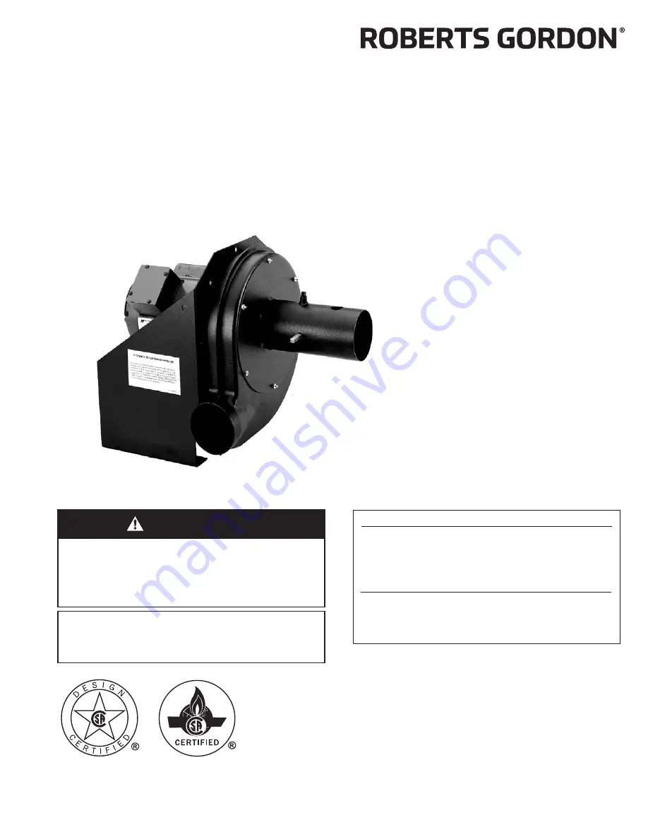
EP-100 Pump

Installation,

Operation &

Service Manual

P/N 127201NA Re

v

. G 3/18

Summary of Contents for EP 100

Page 1: ...cing this equipment Installer Please take the time to read and understand these instructions prior to any installation Installer must give a copy of this manual to the owner Owner Keep this manual in a safe place in order to provide your service technician with necessary information Roberts Gordon LLC 1250 William Street P O Box 44 Buffalo New York 14240 0044 Telephone 1 716 852 4400 Fax 1 716 852...

Page 2: ......

Page 3: ...y Instructions 7 SECTION 6 Pressure Switch Mounting and Wiring 12 6 1 Pressure Switch Installation 12 SECTION 7 Pump Mounting Instructions 13 7 1 Chain Suspension 13 7 2 Wall Mounting 14 SECTION 8 Motor Wiring 17 8 1 Impeller Rotation Direction 17 8 2 EP 100 Wiring 17 SECTION 9 Venting 18 9 1 General Venting Requirements 18 9 2 Venting the Pump 18 9 3 Vent Material Recommendations 18 9 4 Horizonta...

Page 4: ......

Page 5: ...itch Mounting Holes 12 Figure 8 Mounted Pressure Switch 12 Figure 9 Pump Pressure Switch Wiring 12 Figure 10 EP 100 Mounting Chain Suspension 13 Figure 11 Wall Bracket Assembly 14 Figure 12 Wall Mounting Angle Assembly 15 Figure 13 Wall Mounting 15 Figure 14 Optional Platform Assembly Mounting 16 Figure 15 Horizontal Venting 19 Figure 16 Vertical Venting 20 Figure 17 Condensate Check Valve 21 Figu...

Page 6: ......

Page 7: ...he use of work gloves is recommended Do not attempt to operate the pump until all steps of the installation have been accomplished This pump must be applied and operated under the general concepts of reasonable use and installed using best building practices This equipment is not intended for use by persons including children with reduced physical sensory or mental capabilities or lack of experien...

Page 8: ...EP 100 PUMP INSTALLATION OPERATION AND SERVICE MANUAL 2 of 29 FIGURE 1 Label Placement Description Part Number Severe Injury Label 91012100 Rating Plate Label 91010401 Logo Label 91017200 ...

Page 9: ...ition 2 1 Corrosive Chemicals Roberts Gordon LLC cannot be responsible for ensuring that all appropriate safety measures are undertaken prior to installation this is entirely the responsibility of the installer It is essential that the contractor the sub contractor or the owner identifies the presence of combustible materials corrosive chemicals or halogenated hydrocarbons anywhere in the premises...

Page 10: ...ons Lift assembly by gripping metal pump frame Two people are required weight 62 lbs 28 1 kg This pump has been tested prior to packing The impeller was dynamically balanced before assembly and requires care in handling to avoid damage WARNING Cut Pinch Hazard Wear protective gear during installation operation and service Edges are sharp Failure to follow these instructions can result in injury ...

Page 11: ...ions EP 100 Pump Assembly P N 02719100 Pump Scroll Assembly P N 02757001 Band Clamp 4 10 cm P N 91901300 Pressure Switch P N 90430600K Bird Screen 4 10 cm P N 01365400 2 1 2 S Hook P N 91907302 Flexible Boot 4 5 11 cm P N 91412801 Silicone Rubber Ring P N 91906900 Pump Inlet Assembly P N 02724200 ...

Page 12: ...127201NA EP 100 Installation Operation and Service Manual 1 02724200 Pump Inlet Assembly 1 02757001 Pump Scroll 1 91901300 Band Clamp 4 10 cm 5 91907302 2 1 2 S Hooks 3 91412801 4 5 Flexible Boot 2 91906900 Silicone Rubber Ring 4 92311600 10 24 Keps Locknuts 12 90430600K Pressure Switch 1 02757500 Motor Shaft Seal 1 01365400 Bird Screen 4 10 cm 1 01327500 Damper Assembly 1 01329500 Damper Support ...

Page 13: ... in accordance to National Fire Protection Association NFPA 30A latest revision is required An arrow is affixed to outside of pump scroll to indicate impeller rotation direction The standard impeller rotation is in the counterclockwise direction Pump discharge orientation is viewed from the rear of the motor as shown on Page 8 Figure 3 Note that pump scroll outlet must always be in bottom horizont...

Page 14: ...correct orientation of pump scroll outlet attach pump scroll to pump frame using 10 24 Keps locknuts provided NOTE Periodically spin impeller to be sure that adequate clearance is maintained between impeller blades and pump scroll body Arrow showing direction of rotation located on front of scroll housing Counterclockwise Rotation Standard OUTLET Clockwise Rotation OUTLET ...

Page 15: ...See partial end view on Page 9 Figure 4 Attach inlet assembly onto scroll assembly by using 10 24 Keps locknuts provided FIGURE 4 Pump Assembly Pump Inlet Assembly Impeller Pump Scroll Partial End View Rubber Mounts 10 24 Keps Locknuts 12 Required 1 8 NPT Pipe Coupling Description Part Number Rubber Mounts 91906100 Pump Scroll 02757001 Pump Inlet Assembly 02724200 ...

Page 16: ...led be certain to lock damper in full open position with 1 4 20 Hex Head bolt See Page 10 Figure 5 2 Pump inlet assembly is provided with a 1 8 N P T tapping which is located at the top Use tapping to connect pressure switch P N 90430600K See Page 12 Figure 8 FIGURE 5 Damper Assembly Description Part Number Damper Support Assembly 01329500 Inlet Flange Assembly 02724200 1 4 20 x 1 2 Hex Head Bolt ...

Page 17: ...shaft seal at pre cut score line 2 Wrap shaft seal around motor shaft hub as shown 3 Secure shaft seal in position with adhesive strip provided FIGURE 6 Motor Shaft Seal Installation Motor Shaft Seal EP 100 Motor Pump Frame Motor Shaft Hub Impeller Pump Inlet Assembly Pump Scroll Description Part Number EP 100 Motor 90604600 Motor Shaft Seal 02757500 Pump Scroll 02757001 Impeller 02791601 Inlet Pl...

Page 18: ...t switch to pump frame Thread barbed fitting into threaded hole at pump inlet Cut silicone tube to appropriate length to eliminate the possibility of kinks and securely attach hose to pressure switch and barbed fitting FIGURE 8 Mounted Pressure Switch FIGURE 9 Pump Pressure Switch Wiring Pressure Switch Mounting Holes located on both sides of pump frame Barbed Fitting Silicone Hose Pressure Switch...

Page 19: ...n The standard method of mounting the EP 100 pump is suspending it from a chain and venting through the roof For CRVSF Series only a minimum of 18 45 cm ceiling clearance in accordance to National Fire Protection Association NFPA 30A latest revision is required FIGURE 10 EP 100 Mounting Chain Suspension ...

Page 20: ... as shown on Page 14 Figure 11 and Page 15 Figure 12 The two mounting angles form a mounting platform to which the pump will be attached Fix mounting frame to wall using anchors Select an anchor that will give ultimate pull out strength equal to or greater than 2000 lbs FIGURE 11 Wall Bracket Assembly Mounting Angle Hex Head Bolt Flat Washer Lockwasher Hex Nut Flat Washer Description Part Number M...

Page 21: ...CTIONS 15 of 29 7 2 2 Mounting Platform Angle Assembly Mount pump using mounting angles on Page 15 Figure 12 FIGURE 12 Wall Mounting Angle Assembly FIGURE 13 Wall Mounting 7 18 cm 11 5 29 cm 4 5 Silicone Rubber Rings and Band Clamps ...

Page 22: ...a platform suspended from the ceiling or for noise reduction in an enclosure FIGURE 14 Optional Platform Assembly Mounting Mounting Angle 4 Hex Head Bolt Flat Washer Lockwasher Hex Nut Flat Washer 11 5 or 7 29 or 18 cm Description Part Number Mounting Angle Package 01312102 Mounting Angle 01365000 Hex Bolt 5 16 x 3 4 93413912 Flat Washer 95211600 Lockwasher 96411600 Hex Nut 92113900 ...

Page 23: ...00 Wiring The EP 100 motor is wired for 1 Ø 115 V 60 Hz operation However the motor can be rewired for 230 V operation by changing motor connections as indicated by the diagram on motor For proper motor wiring follow manufacturer s wiring diagram located on motor Motor operation can be changed from counterclockwise to clockwise as shown on Page 8 Figure 3 When controlled by a CORAYVAC Heating Cont...

Page 24: ...re 16 Corrosion resistant pipe is required Both horizontal and vertical venting must be supported by suitable hangers Vent lengths are allowed as follows 9 3 Vent Material Recommendations 1 Porcelain coated tubing 4 10 cm O D P N 9141030D 2 Heat treated aluminized tubing 4 10 cm O D P N 91409408 3 Single wall flue pipe corrosion resistant minimum 26 Ga Not suitable for modulating and condensing sy...

Page 25: ...ump to the point of discharge Vent terminal opening must extend beyond any combustible overhang Install vent terminal at a height sufficient to prevent blockage by snow Protect building materials from degradation by flue gases Any portion of flue pipe passing through a combustible wall must be dual insulated and an approved thimble must be used FIGURE 15 Horizontal Venting and Silicone Rubber Ring...

Page 26: ... flue pipe is equal to total of vertical and horizontal length Seal all discharge pipe joints with high temperature silicone adhesive Vertical venting for CRVSF systems is not recommended Vertical venting for CRVSF systems is not recommended FIGURE 16 Vertical Venting 6 15 cm Bird Screen Optional NOTE Vacuum loss may occur when using vent caps The use of bird screen to cover vent terminations is r...

Page 27: ...f the one inch threaded hole is plugged This arrangement will permit drainage of condensate through the pump and outside via horizontal pitched discharge line The condensate trap assembly in the discharge line can be eliminated if the discharge line is horizontal through the wall and pitched down at least one inch per foot A condensate trap on the discharge side is required if there is a vertical ...

Page 28: ...l condensate is 1 8 gal h the condensate neutralization tube which is closest to and higher than the calculated gal h value is P N 01327002 NOTE Condensate neutralization tubes must be replaced yearly every 2000 operating hours Check condensate water pH level and replace tubes if water level is below pH 6 To order replacement see the chart below Radiant Tube Length average distance between burners...

Page 29: ...Calculated gal h Description Part Number Less than 2 Condensate Neutralization Tube 200 01327002 Less than 6 Condensate Neutralization Tube 600 01327003 Less than 10 Condensate Neutralization Tube 1000 01327004 Less than 20 Condensate Neutralization Tube 2000 01327005 ...

Page 30: ...lectrical venting suspensions and overall pump condition are some of the areas requiring inspection Please see Page 25 Section 10 3 for suggested items to inspect 10 2 To Change the Motor and or the Impeller 1 Disconnect electrical before servicing 2 Remove pump boots from inlet and outlet of scroll assembly disconnecting pump from tailpipe and vent pipe 3 To remove motor or impeller scroll and in...

Page 31: ... and Vent Pipe Venting must be intact Using a flashlight look for obstructions cracks on pipe gaps in sealed areas or corrosion Area must be free of dirt and dust or blockage Remove any carbon deposits or scale using a wire brush Replace pipe if there are any holes due to corrosion Seal any gaps in venting to prevent condensate leakage Pump Scroll Impeller and Motor Compressed air or a vacuum clea...

Page 32: ...tor 1 3 H P 90604600 9 Impeller 02791601 2 Bird Screen with Clamp 01312200 10 Inlet Flange Assembly 02724200 3 Ground Strap 01370200 11 10 24 Keps Nut 92311600 4 Rubber Mount for Motor 91906100 12 1 4 20 x 1 2 Hex Head Screw 93413008 5 5 16 18 Hex Nut 92113900 13 1 4 External Tooth Washer 96211500 5 5 16 Flat Washer 95211600 14 5 16 Flat Washer 95211600 5 5 16 Helical Spring Washer 96411600 15 Dam...

Page 33: ...upling E0009356 4 Aluminized Non Heat Treated 10 Tube 91409403 4 Aluminized Tee 01330203 6 Aluminized Non Heat Treated 10 Tube 91409420 6 Aluminized Tee 01330204 4 Coated 10 Tube 9141030D 4 Coated Tee 0133022D Aluminized Tube adapter 6 dia x 4 dia 91418200 6 Coated Tee 0133025D 6 Tube and Reflector Hanger 91240010 4 Aluminized Cross 01330903 4 Drain Cap 02718851 6 Aluminized Cross 01330904 6 Drain...

Page 34: ... lbs 340 kg See Page 11 Figure 6 12 3 Controls Specifications Time switches thermostats etc can be wired into electrical supply External controls supplied as an optional extra See the heaters Installation Operation and Service Manual for details C B G A E D F dia Pump Specifications Model EP 100 Horsepower Hp 1 3 Phase Ø 1 Hertz Hz 60 Voltage V 120 230 Full Load Amp A 5 2 2 7 R P M 3490 Motor Fram...

Page 35: ...e and or serial number are removed defaced modified or altered in any way The ownership of the EP 100 PUMP is moved or transferred This warranty is non transferable Roberts Gordon LLC is not permitted to inspect the damaged equipment and or component parts READ YOUR INSTALLATION OPERATION AND SERVICE MANUAL If you have questions about your equipment contact your installing professional Should you ...

Page 36: ......

Reviews: