


SECTION 5: H
EATER
I
NSTALLATION
7
SECTION 5: HEATER INSTALLATION
5.1 General
Heaters are designed for installation above 1.8 m.
These heaters must be installed within the heated
space. Duct delivery systems are not permitted with
axial fans. When handling or supporting the heater
from below, ensure that the weight is taken at the
support points.
5.2 Shelf Mounting and Suspension
For typical suspension,
See Page 7, Figure 2
.
5.3 Wall Mounting
For typical suspension,
See Page 8, Figure 3
.
Heaters blowing parallel to the wall can only be
installed with the service door away from the wall.
The wall mounting brackets must be attached to a
suitable wall through all mounting holes. Screw
sizes less than M10 may not be used. In order for
the wall mounting brackets to adequately carry the
weight of the heater, it must be installed with best
building practice.
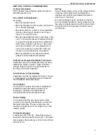
Figure 2: Suspension Methods
Existing cabinet screws must be re-used.
WARNING
Crush
H
a
z
ard
Use
10
mm
steel
drop
rod
minimum.
Failure
of
the
supports
can
result
in
death,
injury
or
property
damage.
Cone Point
Set Pin
Window
Clamp
Unistrut
10 mm
Steel
Drop Rod
Nut
Washer
Riv
Nut
Support Points
Ensure all suspension hardware
is torqued to a minimum
of 27 Nm (20 ft lbs).
NOTE: For vertical installations, use the mounting points on the rear of the unit.
10 mm
Steel
Drop Rod
Washer
Nut
Unistrut
Channel Nut
Shelf Mounting
Brackets
Description
Part Number
Qty.
Shelf Mounting Bracket
Kit
11111510K
Shelf Mounting Bracket (2)
111111510
2
Screw #10 x 1/2"
Type AB Phil HWH Z (2)
94311008
2


