background image

Robin CycFX 8 


23 

MANUFACTURER_LABEL 


DEVICE_LABEL 


SENSOR_DEFINITION 


SENSOR_VALUE 


DISPLAY_LEVEL 


DEVICE_RESET 


DMX_PERSONALITY 


DMX_PERSONALITY_DESCRIPTION 


STATUS_MESSAGES 


STATUS_ID_DESCRIPTION 


DEVICE_HOURS


Please, see the Robe Universal Interface user manual for detail description of RDM operation. 

8. Technical specifications 

Power supply 


• Electronic auto-ranging 


• Input voltage: 100 - 240V AC, 50-60 Hz   


• Fuse: T 5A  


• Max. power consumption*: 150W@230V (power factor=0,94; I=0,64A) 


*Allow for a deviation of +/-10% 
 
• Mains input: CE - max. 16A 


            cETLus - max. 10 A  

• Mains output: CE - max. 15A 


            cETLus - max. 9 A  


Optic & Effects 


• Light source:


Array of  8 x 15W RGBW LED multichips


• Zoom range: x-axis: 12°-43°( at ½ beamu) 

           20°-67° (at 1/10 beamu ) 

                                         y-axis: 8°-40°( at ½ beamu) 

           15°-62°(at 1/10 beamu ) 


• RGBW or CMY  colour mixing 


• Built-in colour macros and pixel effects 


• Adjustable strobe sequences  
•Typical Lumen maintenance: 70% @ 60.000 hours 


Control 


• Setting & Addressing: two-row LCD display & 4 control buttons 


• Control: USITT DMX 512 (RDM support) 


• DMX protocol modes: 4 (14,21,45,53 controll channels) 


• Operations modes: DMX, Stand-alone 


• Manual control of all effects via control panel 
• One editable program, up to 42 steps 

Summary of Contents for Robin CycFX 8 wireless DMX CRMX

Page 1: ...Version 1 4 ...

Page 2: ...ess DMX operation 7 Robin CycFX 8 DMX protocol 8 5 Control menu map 15 6 Control menu 18 6 1 Addressing DMXA 18 6 2 Fixture information Info 18 6 3 Personality Pers 19 6 4 Manual Control Manual 20 6 5 Test program Test Prg 20 6 6 Stand alone St Alone 20 6 7 Reset 21 6 8 Special functions Special 21 7 RDM 22 8 Technical specifications 23 9 Cleaning and maintenance 28 9 1 Replacing a fuse 28 ...

Page 3: ...ibutor or local power company Always disconnect the fixture from AC power before cleaning removing or installing the fuses or any part Do not overload wall outlets and extension cords as this can result in fire or electric shock Make sure that the power cord is never crimped or damaged by sharp edges Check the fixture and the power cord from time to time Do not install the unit near naked flames D...

Page 4: ...xture becomes very hot during operation Allow the fixture to cool approximately 30 minutes prior to manipulate with it Operate the fixture only after having familiarized with its functions Do not permit operation by persons not qualified for operating the fixture Most damages are the result of unprofessional operation Do not attempt to dismantle or modify the unit Please consider that unauthorized...

Page 5: ...can be used instead mounting adapters Pull the safety wire through the attachment point 2 and around the truss For overhead use always install a safety wire that can hold at least 10 times the weight of the fixture You must only use safety wire with screw on carbine Ensure that the structure truss to which you are attaching the fixture is secure 1 Moving head 2 Base of fixture 3 Control panel 4 tu...

Page 6: ...er class one and must be grounded Design of the Robin CycFX 8 allows to connect several fixtures to AC mains power in one interconnected daisy chain using power input and throughput connectors Needed daisy chain cords are stated in the chapter Technical specifications The max number of connected fixtures depends on the AC mains power voltage 15 fixtures at power supply 230V 7 fixtures at power sup...

Page 7: ...n plug is a male 3 pin XLR plug with a 120 Ohm resistor soldered between Signal and Signal 3 4 Wireless DMX operation The wireless version of the Robin CycFX 8 Robin CycFX 8 W is equipped with the Lumen Radio CRMX module and antenna for receiving DMX signal CRMX module operates on the 2 4 GHz band 1 Select wireless DMX input from the menu PErS PErS dM IM dM UL 2 To link the fixture with DMX transm...

Page 8: ...be closed at least 3 sec Shutter channel 13 19 must be at range of 0 31 DMX Corresponding menu items are temporily overrided except DMX Input DMX input Wired DMX DMX input Wireless DMX function is active only10 seconds after switching the fixture on Reserved RGBW colour mixing mode CMY colour mixing mode Tilt speed mode Tilt time mode Blackout while tilt moving Disabled blackout while tilt moving ...

Page 9: ...All pixels No function White 2700 K White 2700 K tungsten emulation White 3200 K White 3200 K tungsten emulation White 4200 K White 5600 K White 8000 K Blue Blue full Red Green White 0 Red 0 Green up Blue full White 0 Light Blue Red 0 Green full Blue full white 0 Red 0 Green full Blue down White 0 Green Red 0 Green full Blue 0 White 0 Red up Green full Blue 0 White 0 Yellow Red full Green full Blu...

Page 10: ...open step step proportional step proportional proportional step proportional step 14 20 20 20 0 255 Dimmer coarse All pixels Dimmer intensity from 0 to 100 proportional 21 21 21 0 255 Dimmer fine All pixels Dimmer intensity from min max proportional 22 22 0 255 Red pixel 1 Red LED saturation control 0 100 proportional 23 23 0 255 Green pixel 1 Green LED saturation control 0 100 proportional 24 24 ...

Page 11: ... LED saturation control 0 100 proportional 41 0 255 Dimmer 5 Dimmer intensity from 0 to 100 proportional 37 42 0 255 Red pixel 6 Red LED saturation control 0 100 proportional 38 43 0 255 Green pixel 6 Green LED saturation control 0 100 proportional 39 44 0 255 Blue pixel 6 Blue LED saturation control 0 100 proportional 45 0 255 Dimmer 6 Dimmer intensity from 0 to 100 proportional 40 46 0 255 Red p...

Page 12: ...ct 3 Step 9 10 Effect 4 Step 11 12 Effect 5 Step 13 14 Effect 6 Step 15 16 Effect 7 Step 17 18 Effect 8 Step 19 20 Effect 9 Step 21 22 Effect 10 Step 23 24 Effect 11 Step 25 26 Effect 12 Step 27 28 Effect 13 Step 29 30 Effect 14 Step 31 32 Effect 15 Step 33 34 Effect 16 Step 35 36 Effect 17 Step 37 38 Effect 18 Step 39 40 Effect 19 Step 41 42 Effect 20 Step 43 44 Effect 21 Step 45 46 Effect 22 Ste...

Page 13: ...5 106 Effect 52 Step 107 108 Effect 53 Step 109 110 Effect 54 Step 111 112 Effect 55 Step 113 114 Effect 56 Step 115 116 Effect 57 Step 117 118 Effect 58 Step 119 120 Effect 59 Step 121 122 Effect 60 Step 123 124 Effect 61 Step 125 126 Effect 62 Step 127 128 Effect 63 Step 129 130 Effect 64 Step 131 132 Effect 65 Step 133 134 Effect 66 Step 135 136 Effect 67 Step 137 138 Effect 68 Step 139 140 Eff...

Page 14: ...5 166 Effect 82 Step 167 168 Effect 83 Step 169 170 Effect 84 Step 171 172 Effect 85 Step 173 174 Effect 86 Step 175 176 Effect 87 Step 177 178 Effect 88 Step 179 180 Effect 89 Step 181 182 Effect 90 Step 183 255 Reserved ...

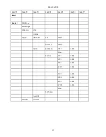
Page 15: ...l 5 Level 6 Level 7 DMXA Set DMXA 001 255 Info POn Time Total Reset DMX In Tilt 0 255 Dimm F 0 255 Temp Current High Res Highest Sw Ver IC 1 IC 2 IC 3 IC 4 Pers DMX Pres Mode 1 Mode 4 DMX In Wired Wireless Tilt Rev On Off T Mode Speed Time T Feed On Off BLC DMC On Off Act BLC T Mov On Off Display Turn ...

Page 16: ... Contrast 0 100 Backlight 0 100 C Cal M On Off C Mix M RGBW CMY Whi Cnt On Off Sil Zom On Off Mic Sens 0 10 19 I Ef Pos Tilt Dimm F Store Defaults Manual Tilt Dimm F Test Prg Sta Alone Music T On Off Auto Run Off Test User Pr Play Test Prg User Prg Pr Edit Step 1 Prg End Tilt Step 42 Copy ...

Page 17: ...l 7 Reset Special RDM Low RDM Hight Wireless Stat Unlink Adjust DMX Val Tilt 0 255 Dimm F 0 255 Calib Cal Mech Tilt C 0 255 Store Cal Col R C 1 0 255 G C 1 0 255 B C 1 0 255 W C 1 0 255 R C 8 0 255 G C 8 0 255 B C 8 0 255 W C 8 0 255 Store Cal Temp Load d C Sw Upd On Off ...

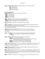
Page 18: ...rder to control each Robin CycFX 8 correctly and independently from any other fixture on the DMX data link If there is no data received at the DMX input the display will start to flash 0001 with actually stored DMX address 6 2 Fixture information Info POn Time Power on time Select this menu to read the number of fixture operation hours Total The item shows the total number of the operation hours s...

Page 19: ...is menu if you wish to close the light output during effect changes P T Mov The menu item allows to close light output while the tilt coordinates are changing Display Display adjusting This menu allows you to adjust the display behaviour Turn This function turns the display by 180 On Off T This function allows you to keep the display permanent on or turn it off two minutes after last pressing any ...

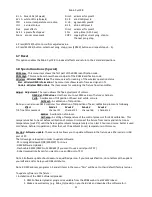
Page 20: ...ilt in test program User The option will start user created program Pr Play Playing program Select this menu to run a user created program in a loop Test Prg The option runs built in test program User Prg The option runs user created program Select the program you wish and press ENTER The selected program starts running By Pressing ENTER again program pauses running Pr Edit Editing program Select ...

Page 21: ...ote you can also use DMX controler for calibration of tilt position of head calibration protocol is following Effect Mode 1 Mode 2 Mode 3 Mode 4 Tilt fine tilt movement channel 15 channel 22 channel 46 channel 54 Cal Col A calibration of colours Cal Temp A setting of temperature of the control processor for LEDs calibration This temperature has to be set before calibration of colours Disconnect th...

Page 22: ... wish to update only later versions of processors check the Incremental Update box Avoid interrupting the process Update status is being displayed in the Info Box window When the update is finished the line with the text The fixture is successfully updated will appear in this window and the fixture will reset with the new software Note In the case of an interruption of the upload process e g power...

Page 23: ...low for a deviation of 10 Mains input CE max 16A cETLus max 10 A Mains output CE max 15A cETLus max 9 A Optic Effects Light source Array of 8 x 15W RGBW LED multichips Zoom range x axis 12 43 at beamu 20 67 at 1 10 beamu y axis 8 40 at beamu 15 62 at 1 10 beamu RGBW or CMY colour mixing Built in colour macros and pixel effects Adjustable strobe sequences Typical Lumen maintenance 70 60 000 hours C...

Page 24: ...0 flashes per second Pre programmed random strobe pulse effects Dimmer Smooth 16 bit dimming from 0 100 Connection DMX data in out Locking 3 pin 5 pin XLR Power In Chassis connector Neutrik PowerCon A type NAC3MPA Power Out Chassis connector Neutrik PowerCon B type NAC3MPB Rigging Via 2 mounting adapters Temperatures Maximum ambient temperature 40 C Maximum housing temperature 70 C Minimum distanc...

Page 25: ...ssories P N 99010420 Omega holder P N1305 1731 Mains Cable PowerCon In open ended 2m P N 1305 1724 Mains Cable PowerCon In Schuko 2m P N 1305 1725 Mains Cable PowerCon In CEE 16A 2m P N 1305 1726 Mains Cable PowerCon In US 2m P N 1305 1727 Daisy Chain PowerCon In Out EU 2m P N 1305 1728 Daisy Chain PowerCon In Out US 2m P N 10980190 Mounting bar CF8 ...

Page 26: ...Robin CycFX 8 26 Beam distribution ...

Page 27: ...Robin CycFX 8 27 ...

Page 28: ... light output very quickly For cleaning use a wet clout or an air jet Do not use solvents or any other aggressive cleaning fluid Maintenance and service operations are only to be carried out by a qualified person Should you need any spare parts please use genuine parts 9 1 Replacing a fuse This replacement has to be realized by a qualified person or ROBE service worker only Specifications are subj...

Page 29: ...Robin CycFX 8 29 ...

Reviews: