background image

21

Operating Instructions - BLUE ARROW Trainer CP S-FHSS RTB 2.4 GHz No. S2537

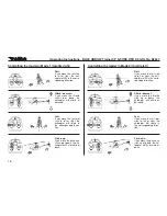
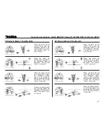
When you move the roll 

stick to left or right, the 

helicopter moves in the 

corresponding direction. 

The control 'sense' re-

mains normal.

When you move the 

throttle stick up or down, 

the helicopter climbs or 

descends. The control 

'sense' is reversed.

When you move the tail 

rotor stick to left or right, 

the helicopter rotates 

(yaws) in the correspon-

ding direction around the 

vertical axis. The control 

'sense' is reversed.

When you move the pitch-

axis stick up or down, the 

helicopter flies forward or 

back. The control 'sense' 

is reversed.

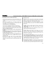
3D flying in Mode 1 (throttle right)

3D flying in Mode 2 (throttle left)

Summary of Contents for BLUE ARROW

Page 1: ...Operating Instructions BLUE ARROW Trainer CP S FHSS RTB 2 4 GHz No S2537 ...

Page 2: ...code which means that they can be bound to FUTABA transmitters which can be operated in S FHSS mode At present these are the following transmitters T6J R2006GS 2 4 GHz FHSS No F4100 T 8J R2008SB 2 4 GHz FHSS S FHSS No F4108 T18MZ R7008SB 2 4 GHz FASSTest M2 No F8073 T18MZ R7008SB 2 4 GHz FASSTest M1 No F8073M1 T 14SG R7008SB 2 4 GHz FASSTest M2 No F8075 T14SG R7008SB 2 4 GHz FASSTest M1 No F8075M1...

Page 3: ...t contents Specification Recommended accessories 6 Model description 7 Receiver functions 8 Receiver settings 9 Preparing the transmitter using a Futaba T8J as example 9 Trouble shooting 10 Transmitter adjustment facilities 10 11 Pre flight adjustments 12 Swashplate adjustments 12 Adjusting the swashplate Main rotor blades 13 Adjusting the main rotor blades 13 Self adhesive marker stripes 13 Check...

Page 4: ... is essential to avoid touching such parts Please bear in mind that motors and speed controllers may become hot when operating It is essential to avoid touching such parts Do not stand close to the hazard area around rotating parts when an electric motor is connected to the flight battery You must also take care to keep all other objects away from moving or rotating parts Observe the instructions ...

Page 5: ...r installing operating and maintaining the model components For this reason we accept no liability for loss damage or costs which are due to the erroneous use and operation of our products or are connected with such operation in any way Regardless of the legal argument employed our obligation to pay compensation is limited to the invoice value of those robbe pro ducts directly involved in the even...

Page 6: ...ly Specification Main rotor diameter 462 mm Tail rotor motor 1627F Tail rotor diameter 113 mm Main motor RK 400SD Length 440 mm All up weight 420 g Gyro six axis Servos metal geared Recommended accessories 1 x F4108 T 8J R2008SB 2 4 GHz FHSS S FHSS 1 x 8566 POWER PEAK B7 EQ BID 12 230 V 1 x 8256 GO3 5 gold charge lead 3 5 mm 1 x 6605GO35 LiPo battery ROXXY Evo 3 1000 30C GO35 Set contents 1 x BLUE...

Page 7: ...gears 6 Ideal model for converting from single rotor to collective pitch control Please note the following points in order to avoid confusion in the model description The model s nose faces away from the pilot the tail boom points towards the pilot The pilot s left hand side is the left hand side of the model and the pilot s right hand side is the right hand side of the model The rotor head faces ...

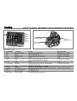
Page 8: ... controller Supplementary circuit board socket S FHSS module To be connected to the speed controller s signal lead for the tail rotor motor Gyro gain adjuster pitch axis Gyro gain adjuster roll axis Servo travel adjuster pitch axis and roll servo Description Pitch axis elevator servo Roll servo Collective pitch servo Unused Throttle Unused Power check SPARE Tail rotor motor Pitch axis sensitivity ...

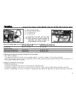
Page 9: ...shing Continuous light Preparing the transmitter using the Futaba T8J as an example Set S FHSS modulation The radio control transmitter must be set to swashplate mode H 1 see T8J instructions 8 1 Parameters page 38 Reverse the roll CH1 pitch axis CH2 throttle CH3 tail rotor CH4 and collective pitch CH6 channels see T8J instructions 7 10 Servo reverse SERVO REV page 20 Binding the transmitter to th...

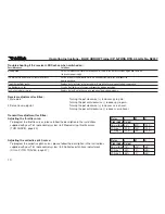
Page 10: ...djustment COLL PITCH TRAVEL page 47 Trouble shooting if the receiver LED flashes when switched on Possible causes Binding failed The throttle stick and throttle trim are set incorrectly Transmitter batteries are flat The flight battery is flat Fault in transmitter or receiver Solutions Switch the radio control transmitter and receiver off Now switch the transmitter on again and switch on the recei...

Page 11: ...il rotor gyro please follow the description in the instructions supplied with your T8J radio control system 8 5 Gyro gyro gain page 44 Please note It is essential to connect all the signal leads attached to the speed controller correctly If you neglect this the speed controller could fail Mode Manual Switch MIX SW Pos 0 75 0 Pos 1 50 0 ...

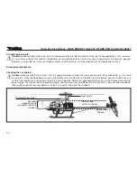
Page 12: ...both motor wires from the speed controller to avoid the motor bursting into life unexpectedly as this could cause injury Place the helicopter on a level surface Move the throttle stick and throttle trim to the bottom position throttle off and set the trims for pitch axis roll and tail rotor to the centre position Switch the radio control transmitter on then connect the receiver power supply The re...

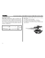
Page 13: ...until the swashplate is straight Adjusting the main rotor blades blade tracking The purpose of this adjustment is to avoid imbalance in the main rotor blades and to set the blade tracking accurately Self adhesive marker stripes Two self adhesive stripes of different colour are applied to the rotor blades in order to simplify the adjustment of blade tracking When the main rotor is spinning you can ...

Page 14: ... two lines the blade tracking must be corrected by adjusting the pushrods at the blade grips 14 Operating Instructions BLUE ARROW Trainer CP S FHSS RTB 2 4 GHz No S2537 Incorrect blade tracking Correct blade tracking The following section describes the main causes for incorrect blade tracking 1 The blades are of different weight 2 The Centre of Gravity of the blades is not identical 3 The length o...

Page 15: ...rtant notes Take off raise the rotor speed slowly and steadily until the model hovers at eye level At the same time adjust the trims until the helicopter is flying stably and hovering over one point At low height approx 10 15 cm above the ground the model cannot be trimmed accurately due to the turbulence generated by the rotor Landing slowly and steadily reduce the throttle setting until the mode...

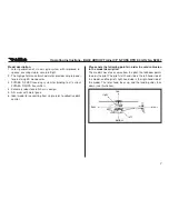
Page 16: ... forward or back Roll If you move the roll stick to left or right the heli copter will fly in the corre sponding direction Climb descent If you move the throttle stick up or down the helicopter will climb or descend Yaw If you move the tail rotor stick to left or right the helicopter will rotate in the corresponding direc tion Pitch axis If you move the pitch axis stick up or down the he licopter ...

Page 17: ...eases If the model responds lethargically to the controls turn the pots clockwise until the helicopter starts to jitter then turn them anti clockwise again until the jitter ceases If you wish to increase agility around the roll and pitch axes turn the ELEV AILE EXT pot clockwise in small increments until the pre ferred level of manoeuvrability is obtained Turn the pot anti clockwise if you wish to...

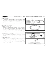
Page 18: ...pter will yaw slightly to the left Correct this unwan ted movement by applying an opposite tail rotor command until the helicopter s tail is again pointing straight at you Your aim should be to stabilise the model in the hover at a height of 1 5 metres and then to land the machine again 2 Practising the roll and pitch axis functions While the model is hovering carefully move the roll stick to righ...

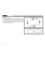
Page 19: ...fident you can speed it up to gain further confidence in the helicopter s flying characteristics Take care to slow the model s descent in good time prior to touch down otherwise the landings could be hard enough to cause damage 2 Practising take off and landing Mark a point on the ground and try to take off and land on this point every time 3 Flying square circuits Flying a square pattern is also ...

Page 20: ...s outlined above it is time to attempt a figure of eight Please note that the pitch axis and roll func tions are effectively reversed when the model is flying towards you Watch the model s altitude through all these manoeuvres it should be as even as possible Repeat the procedure until you are confident flying the figure of eight pattern ...

Page 21: ... move the pitch axis stick up or down the helicopter flies forward or back The control sense is reversed When you move the roll stick to left or right the helicopter moves in the corresponding direction The control sense re mains normal When you move the throttle stick up or down the helicopter climbs or descends The control sense is reversed When you move the tail rotor stick to left or right the...

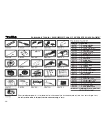
Page 22: ...lrace set S2537020 T CP screw set S2537021 T CP main motor 380PF S2537022 T CP tail rotor motor 1627F S2537023 T CP tail rotor motor lead S2537024 T CP speed controller S2537025 T CP S FHSS receiver S2537026 T CP metal geared servo 6605GO35 LiPo battery ROXXY Evo3 1000 30C GO35 not shown When replacing components it is very important to use the correct type of screwdriver and to tighten the screws...

Page 23: ...robbe com click on the Conformity Declaration logo button which you will find next to the corresponding device description This symbol means that you should dispose of electrical and electronic equipment separately from the household waste when it reaches the end of its useful life Take your unwanted equipment to your local council collection point or recycling centre This requirement applies to m...

Page 24: ...personal liability robbe Modellsport Beteiligungs GmbH Gießen HRB 5793 Managing Director E Dörr Errors and technical modifications reserved Copyright robbe Modellsport 2013 Duplication and copying of the text in whole or in part is only permitted with the prior written approval of robbe Modellsport GmbH amp Co KG 24 Operating Instructions BLUE ARROW Trainer CP S FHSS RTB 2 4 GHz No S2537 ...

Reviews: