background image


- 11 - 


Settings 


The settings menu can be entered from any mode by pressing 

and holding both buttons on the instrument or holding the mode 
button on the MultiSwitch. 

The LCD will show “Keep holding!” with a 

loading bar: 


If the settings are being entered from a mode that also shows a trip, 
the LCD will present the option to reset the trip or enter the settings: 


Use the up and down buttons of the GFX or MultiSwitch to move the 
cursor up and down. Press the two buttons together, or press the 
mode button on the MultiSwitch, to make your selection. 

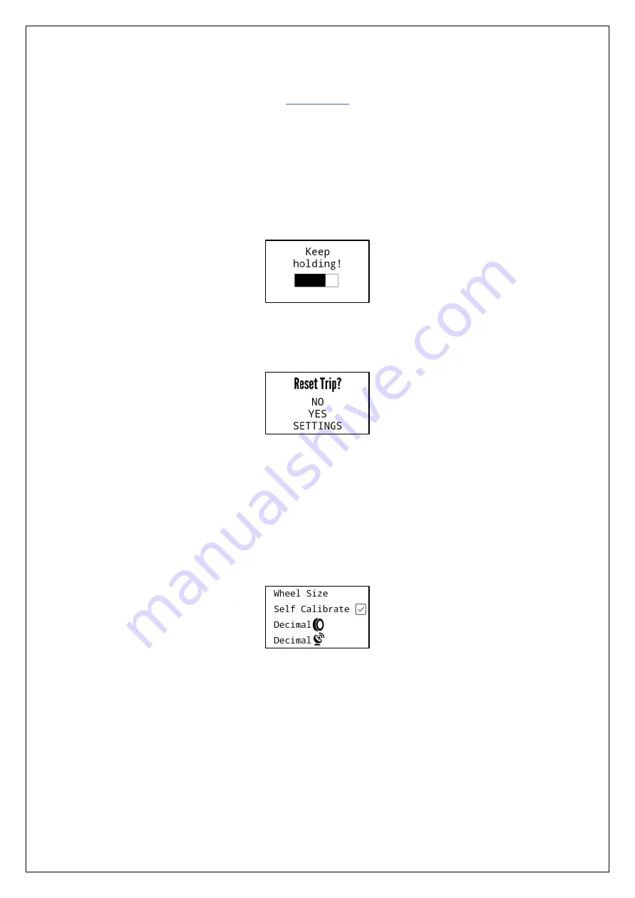
Once inside the menu, you will be presented various settings that 
can be modified: 


Use the up and down buttons to move the cursor and press both 
together to make your selection. 

To  leave  the  settings  menu  and  to  return  to  the  previous  active 
mode, 

move the cursor to “EXIT” and select it.


NOTE: The settings will be automatically exited after 30s of inactivity 

Summary of Contents for TripMaster GFX v2 Pro

Page 1: ...USER MANUAL TripMaster GFX v2 Pro Firmware v2 2...

Page 2: ...nt Consumption 4 Mounting Position 5 GPS Antenna Reception 6 Software Functions 7 Modes 8 Button Control Legend 9 Mode Controls 10 Settings 11 Setting Options 12 Setting Descriptions 13 CAP Assist Fun...

Page 3: ...was paid to ensure the best possible readability and ease of use for the user whilst offering as many functions as possible The new TripMaster GFX v2 Pro was designed implementing the feedback from m...

Page 4: ...ctor 12V power supply Grey male 3 pin connector MultiSwitch remote Black male 3 pin connector wheel sensor Black female 4 pin connector external Garmin GPS NOTE All 4 cables should be connected to the...

Page 5: ...ct polarity will not damage the instrument but it will not function correctly Backup Battery The instrument is equipped with an internal 320mAh capacity Lithium Polymer battery as a backup power sourc...

Page 6: ...ply however it may also be connected to a permanent supply not recommended To awaken the instrument press any button on the device or the connected MultiSwitch or turn the front wheel to trigger the w...

Page 7: ...f the device is on the top of a navigation tower Ideally the top black face of the GFX v2 Pro should not be covered by any materials including metals plastics and carbon fibre ensuring an unobstructed...

Page 8: ...ow for some time during the first use of the device in a new location up to 10 minutes Once the antenna starts to acquire a stable signal the icon will no longer flash and become static Should at any...

Page 9: ...atomic clock signal for the time In total 13 modes are available that can be individually enabled or disabled to suit the rider s preferences 1 GPS Trip 2 GPS Speed 3 GPS Trip GPS Speed a Statistics f...

Page 10: ...8 Modes...

Page 11: ...are two ways to take full control of the instrument 1 Two rubber buttons found on the left side of the unit 2 Externally connected RNS MultiSwitch or compatible remote Short Click Up Short Click Down...

Page 12: ...eel GPS trip timer hold button Switch to next mode Enter settings CAP Assist Set CAP heading as target hold button Switch to next mode Enter settings GPS Speed Wheel Speed Show statistics hold button...

Page 13: ...ettings Use the up and down buttons of the GFX or MultiSwitch to move the cursor up and down Press the two buttons together or press the mode button on the MultiSwitch to make your selection Once insi...

Page 14: ...les CAP Flash CAP will flash when stationary On Off Arrow Choose radius for the arrow to appear in Repeater Mode Yes 500m 1000m Set Clock Manually adjust time GPS is off Set Time Zone Adjust time zone...

Page 15: ...ity Bad Good Perfect and the amount of satellites in lock currently maximum since power up Wheel Size Entering this option will open a new page allowing for the adjustment of all 4 digits of the wheel...

Page 16: ...ntire revolution of the wheel is complete i e the mark on the tire is touching the ground again 4 Place another mark on the ground 5 Measure the distance between the two markings on the ground with a...

Page 17: ...rithm prevents undesirable circumference adjustments when large changes to the trip are made e g readjusting the trip after being lost Set Clock When the instrument is disconnected from its external 1...

Page 18: ...all settings to their default values To leave the page press the down button on the GFX If a factory reset was triggered and the LCD screen is blank press and hold the down button on the GFX to restar...

Page 19: ...ently shown CAP value as the target CAP which is then saved and shown in the bottom left hand corner This projects an endless virtual line to the horizon to which the arrow of the GFX will now point t...

Page 20: ...n of the next waypoint The waypoints on the Garmin device may be from a route multiple waypoints or a single waypoint e g POI To make use of this function your Garmin device must be connected with an...

Page 21: ...LE M8 Male Pin Wire Colour Function 1 Red 12V 3 Yellow Signal 4 Black GND NOTE These cables cradles are also available for purchase as a finished set Please contact us or your reseller for more detail...

Page 22: ...as accurate as the wheel trip There are many external factors involved concerning the accuracy of the GPS signal acquired by the antenna An obstructed view to the sky like from trees in a forest or e...

Page 23: ...21 Software Revisions Version Released Details v2 1 August 2020 Initial Release v2 2 February 2021 Bug fix serial number display Add Mode GPS Trip CAP...

Page 24: ...22 Technical Dimensions...

Reviews: