background image


i -61 

Installing a memory module (DIMM) into the system 

 
To install the DIMM, do the following: 
1. 

Turn OFF the computer. Unhook the AC cord and all 

cables/devices attached to the notebook. 
2. 

Place your hand on a large metal object momentarily to 

discharge any static electricity. 
3. 

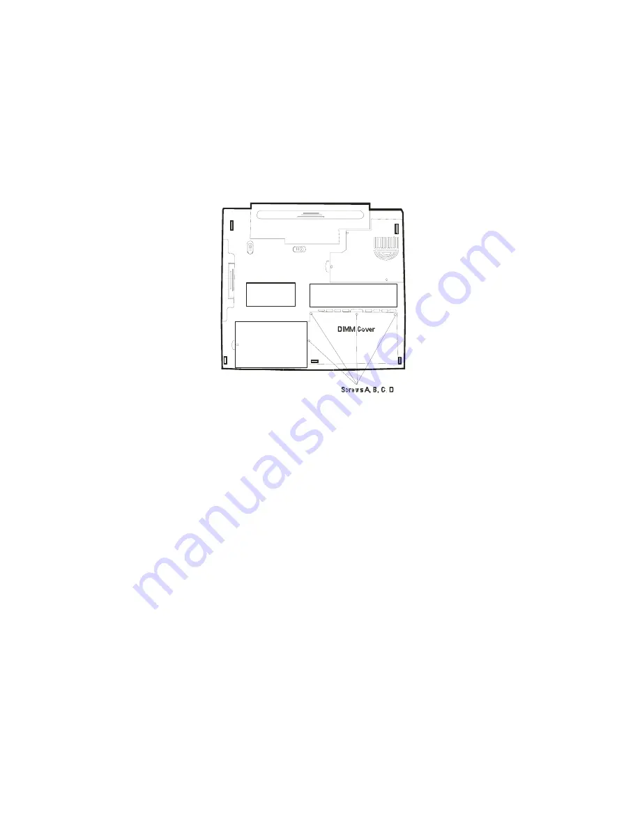
Find Screws A, B, C, D on the bottom side. The screws 

may be different, so note their positions. 


4. 

The DIMM sockets are now revealed as shown below. 


Summary of Contents for NB3000

Page 1: ...ows 95 98 ME 2000 NT XP are trademarks of Microsoft Corporation Product names mentioned herein may be trademarks and or registered trademarks of their respective owners companies The software describe...

Page 2: ...Keys 1 16 Windows Keys 1 17 Embedded Numeric Keypad 1 17 Touch Pad with Page Up Page Down Function 1 18 Graphic Subsystem 1 19 Adjusting the Display Brightness 1 19 Extending the Life of the TFT Displ...

Page 3: ...tery Pack 3 4 5 Charging the Battery and Charging Time 3 5 Checking the Battery Level 3 6 Prolonging the Battery s Life and Usage Cycles 3 6 Using Windows Power Options and AMD PowerNow Technology 3 7...

Page 4: ...s 5 10 Memory Problems 5 11 Modem Problems 5 12 Network Adapter Ethernet Problems 5 13 PC Card PCMCIA Problems 5 14 Performance Problems 5 15 Printer Problems 5 16 Firewire IEEE1394 and USB2 0 Problem...

Page 5: ...S and symbols are used For instance Start Settings Control Panel Display means clicking the Start icon first then the Settings then the Control Panel then the Display icon When you need to make a sel...

Page 6: ...r Do not subject the computer to adverse shock and vibration Do not expose the computer to dust and dirt Do not place objects on top of the computer to avoid damaging the computer Do not place the com...

Page 7: ...tebook This Notebook uses exclusively the AC adapter LSE0202A2090 or LITE ON PA 1900 05 or LISHIN9901A2070 When cleaning the computer observe these steps 1 Power off the computer and remove the batter...

Page 8: ...by the BIOS Chapter 3 Battery Power Power Management In this chapter you will learn the fundamentals of power management and how to use them to achieve longer battery life Chapter 4 Upgrading Your Co...

Page 9: ...i 9 C H A P T E R O N E GETTING TO KNOW THE BASICS This chapter introduces the features and components of the computer...

Page 10: ...p to 266MHz front side bus bandwidth for unparalleled performance Advanced Graphic Engine An integrated VIA S3 Graphics ProSavageDDR 2D 3D video processor for high performance graphics The advanced gr...

Page 11: ...rk and 56K modem Firewire IEEE1394 1394a and USB2 0 ports In addition to a full array of built in I O ports the computer offers IEEE1394 for ultra high speed connection to high bandwidth digital video...

Page 12: ...tch The LCD latches lock unlock the LCD panel 2 LCD Display The panel is where the system content is displayed 3 Suspend Status LED Flashing green light indicates the notebook is in suspend mode See t...

Page 13: ...d menu Press the power suspend button or any key to return from the suspend mode See Section 3 for more details on system suspend function The button has a built in LED to indicate the system ON statu...

Page 14: ...Key Email Quick Key My Favorite Quick Key and Search Quick Key in Windows 98 you must install the special Quick Keys application contained in the factory driver utility CD d Utility Qkeys SETUP EXE 1...

Page 15: ...Card Eject Button The slot is where PC Card PCMCIA is inserted Press the eject button to release the PC Card 18 Firewire IEEE1394 1394a Port This is a high speed serial data port You may connect any...

Page 16: ...purpose 24 Ventilation Grill The fan grill is where air is exchanged to dissipate the internal heat Do not block this airway completely 25 Built in Stereo Speakers The built in speakers output the so...

Page 17: ...an grill is where air is exchanged to dissipate the internal heat Do not block this airway completely 2 Battery Pack The battery pack is a built in power source for the notebook Slide the battery latc...

Page 18: ...Button and Manual Eject Key Hole If your computer comes with DVD ROM you may play DVD movies or regular CD ROM disk If it comes with CD RW drive you may save data onto a CD R CD RW disk Press the eje...

Page 19: ...notebook Slide the battery latch to release the battery pack 2 Ventilation Grill The fan grill is where air is exchanged to dissipate the internal heat Do not block this airway completely 3 Memory Ex...

Page 20: ...how to install the optional wireless LAN card and go to later section in this chapter to learn the basic functions of the wireless LAN card 4 Hard Disk Drive Bay This is where the hard disk drive is...

Page 21: ...ge for the computer 4 AC Plug The AC plug plugs to the AC wall outlet Warning Make sure you are using a standard 3 prong AC wall socket with a ground pin If not you may feel a slight tingling sensatio...

Page 22: ...llowing section describes its indication System Status Indicator LED Graphic Symbol Indication Green light indicates the hard drive is being accessed Green light indicates the optical drive is being a...

Page 23: ...r is currently low Blinking orange light indicates the battery is being charged the system is OFF Blinking orange light indicates the battery is being charged the system is ON Persistent green light i...

Page 24: ...F7 Increases Display Brightness Fn F8 Decreases Display Brightness Num Lock Enables the embedded keypad to work in numeric mode The keys act like numeric keypads in a calculator Use this mode when yo...

Page 25: ...up the popup menu for the application similar to a click of the right mouse button Embedded Numeric Keypad Press Num Lock to enable the embedded numeric keypad The numbers are printed in upper right...

Page 26: ...e Up Down Button Equivalent Tapping Action Execution Click twice quickly Tap twice at the same speed as double clicking the mouse button Selection Click once Tap once Drag Click and hold to drag the c...

Page 27: ...ity overall system performance may suffer See Section 2 on how to increase or decrease the graphic memory Adjusting the Display Brightness The notebook uses special key combinations called hot keys to...

Page 28: ...change to suspend mode when not in use Opening and Closing the Display Panel To open the display slide the LCD latch to the right and lift up the lid Then tilt it to a comfortable viewing position To...

Page 29: ...rag the volume control bar up or down to adjust the volume 3 To temporarily silence the speaker without changing the volume setting click Mute Adjusting the Audio Volume Using the Volume Dial Rotate t...

Page 30: ...he rear side of the computer 2 Plug the other end of the line into the analog phone wall outlet Depending on where your computer is used you may need to change settings in the modem Correct setting wi...

Page 31: ...nto the network connector until the connector snaps securely into the receptacle 2 Either connect the other end of the cable to an RJ 45 jack wall outlet or to an RJ 45 port on a UTP concentrator or h...

Page 32: ...R T W O BIOS SETUP AND SECURITY FEATURE In this chapter you will learn how to enter the BIOS Setup Menu and manipulate various hardware control settings You will also learn how to use the built in se...

Page 33: ...rd operations However there are occasions when you may be required to modify the default settings in the BIOS For example you may need to configure the BIOS power management APM settings if you are us...

Page 34: ...it the BIOS It takes a few seconds to record changes in the CMOS BIOS Action Keys Function Key Command Description ESC Exit Leaves a sub menu to return to the previous menu OR exits the BIOS setup whi...

Page 35: ...tup Main Menu AMIBIOS HIFLEX SETUP UTILITY VERSION x xx c 2000 AMERICAN MEGATRENDS INC ALL RIGHTS RESERVED STANDARD CMOS SETUP ADVANCED CMOS SETUP POWER MANAGEMENT SETUP AUTO DETECT HARD DISKS CHANGE...

Page 36: ...s selected Sec Master Sec Slave Auto CD DVD ARMD Not Installed User The secondary master controls the CD ROM DVD ROM drive Normally Auto is selected Boot Sector Virus Protecti on Disabled Enabled To e...

Page 37: ...hanced IDE feature you may still change the value manually 32 Bit Mode Select On to allow data transmission in 32 bit format PIO Mode Normally use Auto To let BIOS decide the PIO mode setting If the s...

Page 38: ...ROM drive Advanced CMOS Setup Item Selections Sub menu Description 1st Boot Device Set the type of device for the 1st drive BIOS attempts to boot from Note IDE 0 is the hard disk drive If Intel UNDI...

Page 39: ...system boots VGA Frame Buffer Size 8 16 32 MB This option allows user to define the amount of system memory to be used as display memory or buffer Share memory size may be set up to 50 of the total s...

Page 40: ...Suspend On Off When the power button is pressed the system is turned off Suspend When the power button is pressed the system enters the suspend mode Note The Suspend Mode selection in BIOS only applie...

Page 41: ...n or memorize them If you lost the passwords the computer may need to be sent back to the factory or to an authorized service dealer to reset the passwords Auto Detect Hard Disk When selecting this op...

Page 42: ...i 42 C H A P T E R T H R E E BATTERY POWER POWER MANAGEMENT In this chapter you will learn the fundamentals of power management and how to use it to achieve longer battery life...

Page 43: ...tivity to save power Efficient power management can help you work longer sessions before having to recharge the battery The Battery Pack When the notebook operates on battery power the Battery LED ind...

Page 44: ...n occurs at 3 power remaining The power LED indicator blinks and the system beeps at 4 second interval When the notebook warns you of its low battery condition you will have about 5 10 minutes to save...

Page 45: ...k To Remove the Battery Pack 1 Place the notebook bottom side up on a flat and secured surface 2 Locate the battery latch Pull the latch toward the direction shown by the arrow and hold 3 Pull out the...

Page 46: ...ook and the latch locks in place Charging the Battery and Charging Time To charge the battery while the battery pack is in the notebook plug the AC adapter into the notebook and an electrical outlet T...

Page 47: ...l outlet is available This will ensure uninterrupted computing Purchase an additional battery pack Store the battery pack in room temperature Higher temperature tends to deplete the battery s power fa...

Page 48: ...n application does not require full performance the processor s speed and voltage are lowered and therefore significant amounts of power can be saved However the processor can instantaneously respond...

Page 49: ...and voltage to conserve power as much as possible In this dialog box you can manually set the LCD and hard drive s time out values in the Plugged in column and in the Running on batteries column Lowe...

Page 50: ...s are saved to the hard disk drive after a period of inactivity defined by the user No power or very little power is drawn from the battery module under this mode However depending on how much RAM tha...

Page 51: ...i 51 Note Do not install or remove the memory module when the system is in the suspend mode Note Actual dialogue box shown above may appear slightly different...

Page 52: ...b In the pull down menu select how you wish the power button to work as Note Actual dialogue box shown above may appear slightly different Warning In the When I close the lid of my portable computer p...

Page 53: ...Alarms tab in the Power Options Properties box If you wish to hear audible beeps click on the Alarm Action button and put a check on Sound Alarm Note Consult Windows user guide for more information on...

Page 54: ...n at the lower right hand corner of the task bar If you do not see a battery or AC in icon go to Power Options Properties box and click on the Advanced tab Check off Always show icon on the task bar S...

Page 55: ...i 55 C H A P T E R F O U R UPGRADING YOUR COMPUTER In this chapter you will learn how to upgrade the DRAM hard disk drive and to install the optional wireless LAN mini PCI card...

Page 56: ...instructions carefully or have a qualified technician install it for you Damages due to mishandling of this procedure are NOT covered by the manufacture s warranty Warning Apply care when handling th...

Page 57: ...ject momentarily to discharge any static electricity 3 Locate the hard disk drive cover on the bottom of the notebook 4 Unscrew Screw A B C D and remove the DIMM Cover And then remove Screw E and remo...

Page 58: ...Note th ese 4 pins are not connected 6 Locate and remove 4 Screws F HDD T ray S crews F Screw s F 7 Remove the old HDD from the Tray and replace with the new drive Note the green PC board of the hard...

Page 59: ...o nne c to r HDD Co nnec tor No te th ese 4 p ins are n ot con n ected 10 Replace HDD Cover and DIMM Cover and replace Screws A B C D and E Congratulations You have now completed the hard drive upgrad...

Page 60: ...n be 128MB 256MB 512MB or 1024MB in capacity The DIMM is of type DDR SDRAM has 200 pins and runs on 2 5V or 3 3V The DIMM should be PC1600 or PC2100 compliant Warning Memory upgrade is a delicate proc...

Page 61: ...mputer Unhook the AC cord and all cables devices attached to the notebook 2 Place your hand on a large metal object momentarily to discharge any static electricity 3 Find Screws A B C D on the bottom...

Page 62: ...ame time The DIMM should pop up to an angle of 30 degree see diagram below Pull the DIMM module out of the memory socket Store away the DIMM for the future use 6 Install the new DIMM module into the e...

Page 63: ...metal DIMM cover and Screws A B C and D Congratulations You have just completed the memory upgrade When you boot up the computer you should expect to see an increase in DRAM capacity Note Your comput...

Page 64: ...y of the mini PCI card Warning Installing a mini PCI card is a delicate process Please observe the following instructions carefully or have a qualified technician install it for you Damages due to mis...

Page 65: ...l only fit in one direction Align the small notch in the module with the socket on the connector and insert the card at an angle of approximately 30 degrees into the empty socket Then press it firmly...

Page 66: ...section Congratulations You have now completed the mini PCI card installation During the next time the system boots to Windows the system will prompt for driver location Insert the Factory CD ROM and...

Page 67: ...i 67 C H A P T E R F I V E TROUBLE SHOOTING In this chapter you will learn how to solve common hardware and software problems...

Page 68: ...the error continues contact your reseller for service information Before taking further actions consider the following suggestions Check to see if the problem persists when all the external devices ar...

Page 69: ...scanner printer do not function correctly when connected to the system it is usually the device s own problem Consult the device s manufacturer first Some software programs which have not gone through...

Page 70: ...ectly Go to Start Settings Control Panel and double click the Sounds and Audio Devices icon In the Audio page make sure that VIA AC97 Audio Wave is the default playback device Sound cannot be recorded...

Page 71: ...omputer has been subjected to static electricity or physical shock you may have damaged the disk drive The hard drive is making abnormal whining noises You should back up your files as soon as possibl...

Page 72: ...riod the files may be fragmented Go to Start Programs Accessories System Tools Disk Defragmenter to perform a disk defragmentation This operation may take a while Interrupt requests or problems with o...

Page 73: ...sure the disk is firmly seated onto the spindle The disk is damaged or not readable The disk cannot be ejected Normally it takes a few seconds to eject the disk If the disk cannot be ejected it may be...

Page 74: ...e modes The screen is difficult to read The display resolution should at least be set to at least1024x768 for optimal viewing 1 Go to Start Settings Control Panel and double click the Display icon 2 U...

Page 75: ...put If you are connecting an external keyboard to the system the built in keyboard may not work Try restarting the system The characters on the screen repeat while I type You may be holding the keys d...

Page 76: ...the booting procedure even after rebooting it may indicate failure of the CMOS battery If so you need to replace the battery This battery normally lasts two to five years The battery is of type CR203...

Page 77: ...le may not be installed properly Go back to Chapter 4 to review the details of this operation The memory module may be defective The O S issues an insufficient memory error message during operation Th...

Page 78: ...handle such problems Make sure the phone line which the computer is connected to is working Connection difficulties Be sure to disable Call Waiting on the phone line Be sure to have the correct countr...

Page 79: ...e or update the device driver from the factory CD ROM disk or consult Windows manual on how to solve the resource conflict problem Make sure the physical connections on both ends of the cable are good...

Page 80: ...h the edge of the computer Remove and insert the PC card again Make sure there is no IRQ conflict with the card See Windows on line help for solving IRQ conflicts Reboot the computer and see if the pr...

Page 81: ...its CPU clock to protect itself from thermal damage The program appears stopped or runs very slowly Press CTRL ALT DEL to see if an application is still responding Restart the computer This may be no...

Page 82: ...printer powered up and connected first The printer does not print what s on the screen The information displayed on the screen may not exactly be the same as what is printed If the printer prints ext...

Page 83: ...u should see an entry which reads IEEE 1394 Bus host controllers If it does not exist Windows has not detected the host controller or the device driver has not been installed properly If there is a ye...

Page 84: ...i 84 A P P E N D I X A PRODUCT SPECIFICATION...

Page 85: ...us Two 200 pin SO DIMM sockets Max 1 GB Display 14 inch XGA active matrix TFT display with up to 16M colors Integrated S3 ProSavageDDR 256 bit 2D 3D graphics accelerator 4X AGP architecture graphics c...

Page 86: ...6 integrated Ethernet function for 10 100Base TX network standards VT6103L Windows ME 2000 XP Plug and Play compatible Automatic Jam and auto negotiation for flow control Auto Negotiation and Parallel...

Page 87: ...ed 5 25 inch format 12 7mm height swappable module with 8X speed 5 25 inch format 12 7mm height swappable module Optional Purchase 5 25 inch format 12 7mm height swappable module Optional Purchase Key...

Page 88: ...DC in connector One 15 pin VGA connector One PC Card Slot type II One 6 pin PS 2 Port Battery Pack AC Adapter Li ion 8 cell pack 14 8V x 4000 mAh 59 2Wh or Li ion 8 cell pack 14 8V x 4400 mAh 65 1Wh S...

Page 89: ...32bit access Ultra DMA PIO5 Mode support Multi boot capability Microsoft Windows ME 2000 XP Microsoft NT 4 0 Physical Specification 305 W x 270 D x 25 4 H mm 5 3 lbs 2 4 KG with CD ROM Operating Temp...

Page 90: ...i 90 A P P E N D I X B AGENCY REGULATORY NOTICES...

Page 91: ...following measures Reorient or relocate the receiving antenna Increase the separation between the equipment and the receiver Connect the equipment into an outlet on a circuit different from that to wh...

Page 92: ...e nemet pas de bruits radioelectriques depassant les limites applicables aux appareils numeriques de Classe B prescrites dans le reglement sur le brouillage radioelectrique edicte par le Ministere des...

Page 93: ...be a two pole grounded type with a Japanese Industrial Standard C8303 15 A 125 VAC configuration Other Countries The cord set fittings must bear the certification mark of the agency responsible for ev...

Page 94: ...ery Pack Safety The battery pack is intended to use only with this notebook Do not disassemble the pack Do not dispose of the battery pack in fire or water To avoid risk of fire burns or damage to you...

Page 95: ...Radiation Performance Standard and International Standards IEC 825 IEC 825 1 EN60825 EN60825 1 The device is not considered harmful but the following precautions are recommended Do not open the unit A...

Page 96: ...anger of explosion if battery is replaced incorrectly Replace only with the same or equivalent type recommended by the manufacturer Discard used batteries according to the manufacturer s instructions...

Page 97: ...i 97 Die Steckdose muB nahe dem Gerat angebracht und leicht zuganglich sein...

Page 98: ...WITH THE FOLLOWING AC ADAPTER MODEL ONLY PB 5 added Telephone Line Cord Requirement The appropriate utilization of 26 AWG telephone line cord on unit is required CAUTION Always disconnect all telepho...

Reviews: