background image

The installation location must also provide a suitable ground system both for RF and the 
AC power supply, (if used). This is very important safety requirement for any radio trans-
mission equipment but as power increases becomes increasingly important. A good RF 
ground will also help to prevent  any returned RF from causing problems with the equip-
ment. Usually erratic operation of equipment when in transmission may be attributed to 
RF being present or poor RF grounding. Installations where a good RF ground is not pos-
sible like operation above the ground floor may require alternative solutions such as arti-
ficial earths or the connection of 1/4 wave counterpoises to the operating equipment. Cor-
rect RF earthing techniques  are however beyond the scope of this manual. 
 
Mobile use should ensure that the ground connections are well bonded to the vehicle 
chassis ground for best operation. 

Operation: 

  
Before using the amplifier the user must be familiar with all of the controls and be sure 
that it has been connected correctly. Refer to Page 3 of this instruction manual. 
  

Important!! 


Before the amplifier is switched on, (switch 

]

), the power output of the drive radio should 

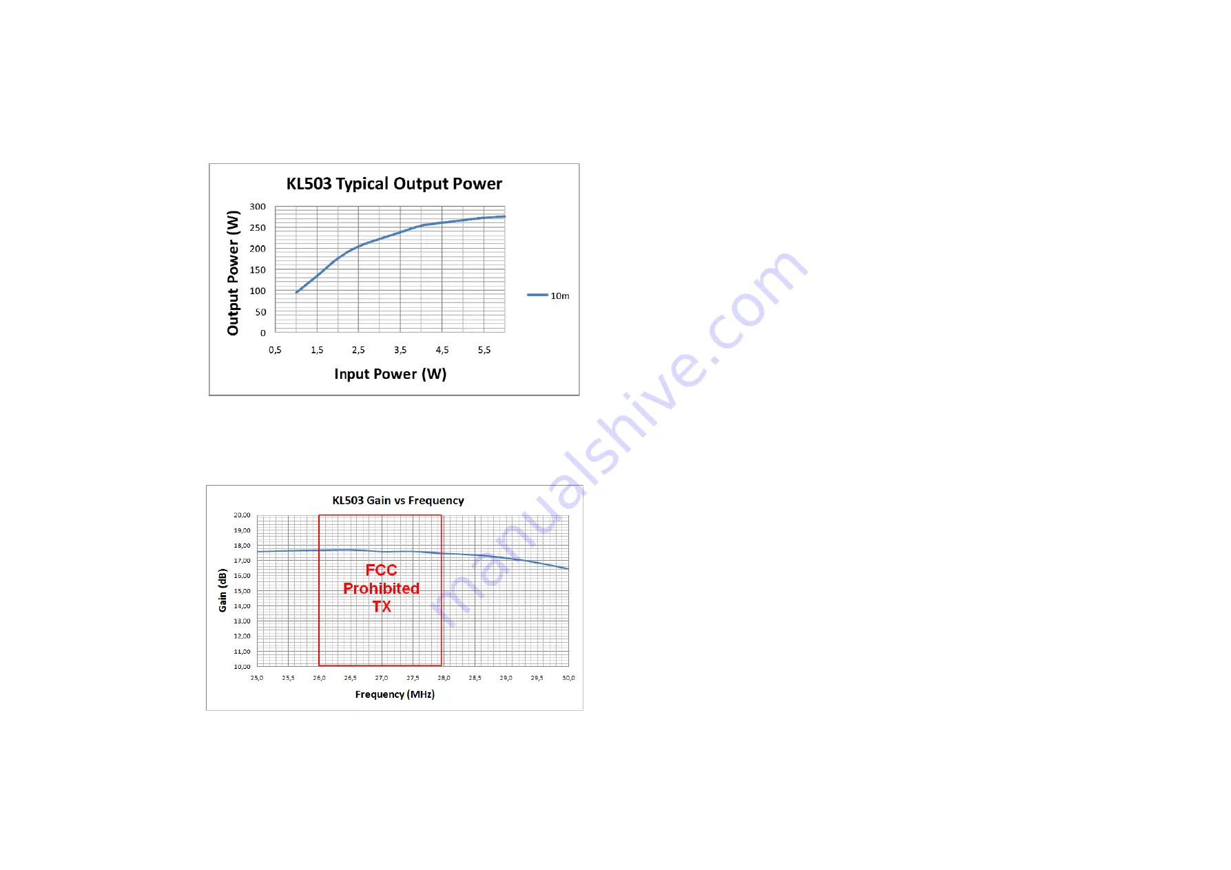
be adjusted correctly if it is capable of outputting a power greater than 6W.  This may be 
done with the amplifier connected but switched off. 6W is the maximum permissible in-
put power to the amplifier, but approximately 4-5W input should be sufficient to realise 
full output, and an input power of  1-5W is OK as it is not necessary to run the amplifier 
at full output if not required. 
  

When the amplifier is switched on LED 

`

 is illuminated. 

  
 The amplifier does not have protection against excessive input power and as such the 
responsibility will be with the user not to overdrive it. Maximum input should not exceed 
6W.  The best performance of the amplifier will be obtained if the amplifier is operated at 
just less than full output which should be achieved with about 4-5W input.  
  
If the drive radio cannot be reduced below 6W then the input attenuator should not be 
used to lower the input to the amplifier. The input attenuator can , and should only be 
used, to reduce the output of the amplifier if required. There are 6 levels of attenuation. 
  
Damage will occur  if the amplifier is operated above 10W input power. 
  

When the amplifier is in transmission LED 

^

 is illuminated. When it is OFF the amplifier 

Summary of Contents for KL503

Page 1: ...ge to the RF power transistors from incorrect use KL503 HF 25 30 MHz Linear Amplifier WARNING Before using this product please read carefully all of the information in this manual or at least the quick start guide To avoid damage or incorrect operation this is extremely important Specifications Operation Frequency 25 30 MHz 10m Amateur HF Bands Modulation Types SSB CW AM FM All narrowband modes Tr...

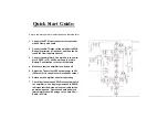
Page 2: ...ble 13 8VDC 1V 40A Power Supply or Auto Battery Pay attention to the correct polarity 4 Make sure that the amplifier is switched off 5 Adjust the Transceivers RF output power to 5W 6W max if it is capable of more than 5W output 6 Switch on the Amplifier and start operating 7 Check that the antenna VSWR is acceptable with the amplifier in use Any large increase in VSWR indicates that the Antenna is...

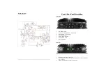
Page 3: ...ceive Pre Amplifier ON OFF Switch 3 Amplifier ON OFF Switch 4 TX indicator LED 5 Pre Amplifier ON LED 6 Amplifier ON LED 7 Input Attenuator 1 RTX SO239 RF input connector 2 DC Input power connector Polarity is marked on the supplied mat ing connector 3 ANT RF Output SO239 Socket to Antenna ...

Page 4: ...switch should be set to SSB This adds a short delay to the release time of the RTX relays so that pauses in speech do not cause the RTX relay to drop out In AM or FM mode the SSB delay switch should be set to AM The amplifier must be connected via the input power connector to a suitable power sup ply of the correct voltage output and sufficient current rating The output should be 13 6 13 8V DC but...

Page 5: ...t Before the amplifier is switched on switch the power output of the drive radio should be adjusted correctly if it is capable of outputting a power greater than 6W This may be done with the amplifier connected but switched off 6W is the maximum permissible in put power to the amplifier but approximately 4 5W input should be sufficient to realise full output and an input power of 1 5W is OK as it ...

Page 6: ...n a few minutes should be avoided to avoid ex cessive transistor junction temperature The exact time for transmission in these modes will depend on numerous factors such as how good the ventilation around the amplifier is if there is sufficient space for freely flowing air to circulate etc If the ambient temper ature is high this will reduce the total time in transmission Common sense should be In...

Reviews: