24 • 35-3001A-10 Oxygen/Carbon Monoxide Sample-Draw Detector
4. Decrease the flow very slowly by turning the sensor flow control valve’s knob counterclockwise
and verify that the low flow alarm is 0.6 SCFH (±0.1).
If the low flow alarm is set too high, turn the pressure switch adjustment screw slightly clockwise.
Repeat steps 3 and 4 if necessary.
5. Use the sensor flow control valve to set the flow to 1.0 SCFH.
6. Make sure the sample-draw detector’s Fail LED is off.
Removing the Particle Filter’s Tubing Stub, if Necessary
A short tubing stub comes factory installed in the particle filter. It is used for connecting the particle
filter to the inlet fitting. If you have installed the particle filter and no longer want it installed, you will
need to remove the particle filter’s tubing stub from the inlet fitting and replace it with tubing.
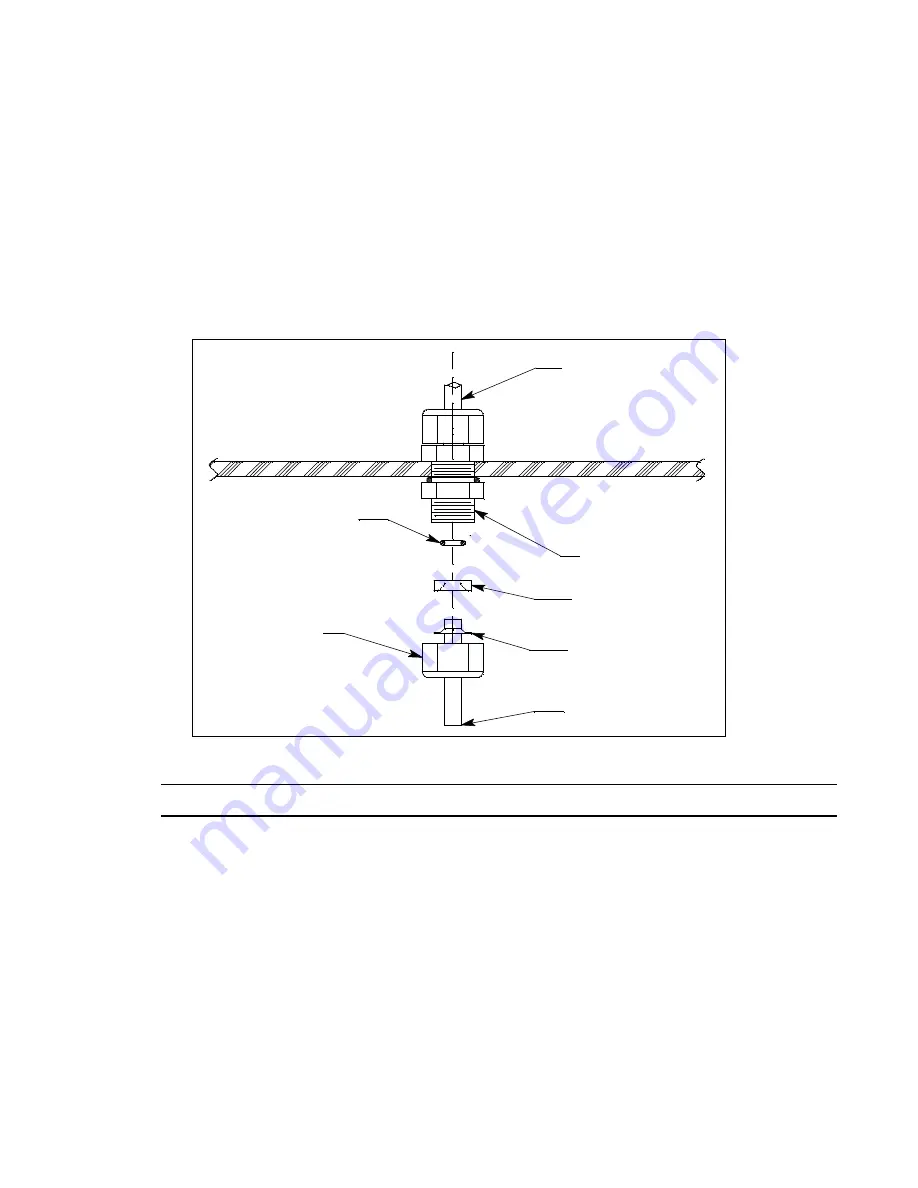
Figure 7: Inlet Fitting with Tubing Stub
CAUTION:
Do not pull the tubing stub downward to remove it.
1. Remove the particle filter’s tubing stub.
2. Unscrew the outside inlet fitting tube nut from the fitting body. The tubing stub should come out
with the tube nut. Be careful not to lose the O-ring that may come out with the tubing stub. If you
do lose the O-ring or if it is damaged, see “Parts List” on page 29 for the spare part number.
3. Push the tubing stub up and out of the front ferrule being careful not to lose the ferrule set. If you
do lose the ferrule set or if it is damaged, see “Parts List” on page 29 for the spare part numbers.
4. Push the new tubing up through the inlet fitting tube nut and replace the ferrule set and the O-ring,
if it came out, in the orientation shown in Figure 7.
5. Screw the inlet fitting tube nut back onto the fitting body. See page 14 for instructions to install a
new piece of tubing into the fitting.
1/4" Tube
Back Ferrule
Front Ferrule
Fitting Body
Outside of Case
1/4" Tube
O-ring
Tube Nut
Inside of Case


