background image


01Series Operator’s Manual

Table of Contents

Maintenance . . . . . . . . . . . . . . . . . . . . . . . . . . . . . . . . . . . . . . . . . . . . . . . . . . . . . . . . . 22

Troubleshooting  . . . . . . . . . . . . . . . . . . . . . . . . . . . . . . . . . . . . . . . . . . . . . . . . . 22
Replacing the Batteries . . . . . . . . . . . . . . . . . . . . . . . . . . . . . . . . . . . . . . . . . . . . 23
Replacing the Sensor . . . . . . . . . . . . . . . . . . . . . . . . . . . . . . . . . . . . . . . . . . . . . 24
Replacing the Sensor Cover and Charcoal Filter . . . . . . . . . . . . . . . . . . . . . . . . 25

Parts List. . . . . . . . . . . . . . . . . . . . . . . . . . . . . . . . . . . . . . . . . . . . . . . . . . . . . . . . . . .  . 27

WARNING: Understand this manual before operating the 01 Series. 

Substitution of components may impair intrinsic safety. 
To prevent ignition of a hazardous atmosphere, batteries 
must only be changed in an area known to be 
nonhazardous. This unit has not been tested in an 
oxygen enriched atmosphere (above 21%).

Summary of Contents for 01-Series

Page 1: ...www rkiinstruments com 01 Series Operator s Manual Part Number 71 0093RK Revision A Released 2 2 11 ...

Page 2: ...calibration and maintenance of the gas monitor is essential for proper operation and cor rect readings Please calibrate and maintain this instrument regularly Frequency of calibration depends upon the type of use you have and the sensor types Typical calibration frequencies for most applications are between 1 and 3 months but can be required more often or less often based on your usage ...

Page 3: ...s warranty indicates the full extent of our liability and we are not responsible for removal or replacement costs local repair costs transportation costs or contingent expenses incurred without our prior approval THIS WARRANTY IS EXPRESSLY IN LIEU OF ANY AND ALL OTHER WARRANTIES AND REPRESENTATIONS EXPRESSED OR IMPLIED AND ALL OTHER OBLIGATIONS OR LIABILITIES ON THE PART OF RKI INSTRUMENTS INC INC...

Page 4: ... Buttons 8 Printed Circuit Boards 8 Alarm Lights 9 Buzzer 9 Vibrator 9 Batteries 9 Start Up 10 Start up Procedure 10 Performing a Fresh Air Adjustment 10 Turning Off the 01 Series 10 Operation 11 Measuring Mode 11 Displaying the Peak STEL and TWA CO 01 and HS 01 11 Displaying the Min and Max OX 01 12 Alarms 13 Alarm Points 16 Displaying and Adjusting the Alarm Points 16 Calibration 19 Calibration ...

Page 5: ...sor Cover and Charcoal Filter 25 Parts List 27 WARNING Understand this manual before operating the 01 Series Substitution of components may impair intrinsic safety To prevent ignition of a hazardous atmosphere batteries must only be changed in an area known to be nonhazardous This unit has not been tested in an oxygen enriched atmosphere above 21 ...

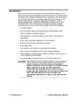
Page 6: ...vibration alarms Microprocessor control for reliability ease of use and advanced capabilities Peak STEL and TWA indication for CO 01 HS 01 Minimum and maximum indication for OX 01 Over range alarm Gas battery sensor failure and system failure alarms Over 3 000 hours operation on one set of alkaline batteries CSA certified for intrinsic safety in Class I Division I Groups A B C and D hazardous atmo...

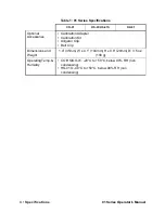
Page 7: ... Method Diffusion Diffusion Diffusion Response Time T90 in 30 seconds T90 in 30 seconds T90 in 20 seconds Accuracy 5 of reading or 5 ppm CO whichever is greater 5 of reading or 2 ppm H2S whichever is greater 0 5 O2 Indication 7 Segment Digital LCD Safety Regulatory C US 186718 CSA classified C US as Intrinsically Safe Exia Class I Groups A B C D Temperature Code T3 Power Two AAA size Alkaline Batt...

Page 8: ...ibration Kit Alligator Clip Belt Clip Dimensions and Weight 1 4 35mm W x 4 1 104mm H x 0 8 20mm D 3 5 oz 100 g Operating Temp Humidity CO HS OX 01 20 C to 50 C below 90 RH non condensing HS 01S 40 C to 50 C below 90 RH non condensing Table 1 01 Series Specifications CO 01 HS 01 HS 01S OX 01 ...

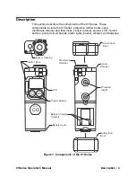
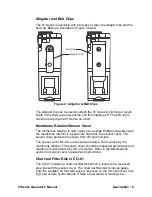
Page 9: ... membrane retainer and filter disks sensor retainer sensor LCD control buttons printed circuit boards alarm lights buzzer vibrator and batteries LCD Control Buttons Alarm Lights Buzzer Opening Membrane Retainer Sensor Retainer Battery Cover Battery Charging Contacts POWER MODE AIR CO 01 CO Sensor End Boot Battery End Boot Threaded Inserts Figure 1 Components of the 01 Series ...

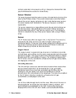
Page 10: ...d in place by the sensor retainer the top of the case for the 01 Series and two screws The sensor is protected from dirt and moisture by the sensor cover The sensor cover is secured by a membrane retainer and a single screw In the case of the CO 01 a charcoal filter is provided under the sensor cover to protect the CO sensor from hydrogen sulfide and certain hydrocarbons To the left of the sensor ...

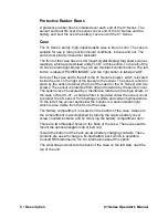
Page 11: ...per like filter disk the sensor cover The sensor cover protects the sensor from dirt and moisture The sensor cover fits into a recessed area and is held in place by the membrane retainer The sensor cover should be inspected periodically and replaced if contaminated by dirt or moisture Refer to the Maintenance section for sensor cover replacement instructions Charcoal Filter Disk in CO 01 The CO 01...

Page 12: ...the three 01 Series models use different detection principles as described below Oxygen Sensor The oxygen sensor is a galvanic type of sensor A membrane covers the cell and allows gas to diffuse into the cell at a rate proportional to the partial pressure of oxygen The oxygen reacts in the cell and produces a voltage proportional to the concentration of oxygen The voltage is measured by the 01 Ser...

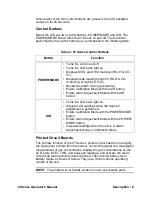
Page 13: ...cuit if an alarm point has been reached They monitor battery level battery failure and sensor failure They also control various operating modes of the unit NOTE The printed circuit boards contain no user serviceable parts Table 2 01 Series Control Buttons Button Function POWER MODE Turns the unit on and off Turns the LCD back light on Displays STEL and TWA readings HS 01 CO 01 Displays peak readin...

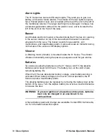
Page 14: ...uring normal use of the various LCD display options Vibrator A vibrating motor vibrator is mounted inside the 01 Series The vibrator vibrates momentarily during the power up sequence and for gas alarms Batteries Two AAA size alkaline batteries run the 01 Series At 25 C the alkaline batteries last at least 3 000 hours The battery icon on the LCD shows remaining battery life When the 01 Series detec...

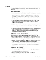
Page 15: ...e concentration of the target gas is displayed on the LCD The 01 Series is now in Measuring Mode The target gas concentration is displayed The backlight turns off after 20 seconds Performing a Fresh Air Adjustment Before using the 01 Series set the fresh air reading Performing this adjustment ensures accurate gas readings in the monitoring environment 1 Find a fresh air environment of normal oxyge...

Page 16: ... The target gas concentration is displayed below the battery icon On the CO 01 CO is displayed in parts per million ppm On the HS 01 H2S is displayed in ppm On the OX 01 oxygen is displayed as volume percent Displaying the Peak STEL and TWA CO 01 HS 01 You can display the Peak STEL and TWA readings on the CO 01 and HS 01 when the 01 Series is in Measuring Mode using the POWER MODE button STEL is a...

Page 17: ...ng the peak gas reading the unit will return to Measuring Mode automatically and the backlight will turn off Displaying the Min and Max OX 01 You can display the minimum Min and maximum Max readings on the OX 01 when the it is in Measuring Mode using the POWER MODE button The Min and Max readings are cleared when the unit is turned off 1 Make sure the OX 01 is in Measuring Mode The oxygen concentr...

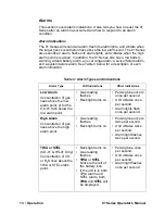
Page 18: ...s and Indications Alarm Type LCD Indications Other Indications Low Alarm Concentration of gas rises above the low alarm point or for the OX 01 falls below the low alarm point Gas reading flashes Back light turns on Pulsing tone occurs once per second Unit vibrates once per second Alarm lights flash once per second High Alarm Concentration of gas rises above the high alarm point Gas reading flashes...

Page 19: ...ries Or there could be a problem with the unit Gas reading replaced by blinking brackets Back light turns on Pulsing tone occurs once per second Unit vibrates once per second Alarm light flashes Low Battery Warning Last remaining bar on the right in battery icon flashes None Dead Battery Alarm Gas reading replaced by FAIL Battery icon flashes Double pulsing tone two pulses in quick succession occu...

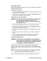
Page 20: ...r the alarm condition has cleared 3 Calibrate the 01 Series as described in the calibration section of this manual 4 If the over range condition continues you may need to replace the sensor 5 If the over range condition continues after you have replaced the sensor contact RKI Instruments Inc for further instructions Responding to Battery Alarms WARNING The 01 Series is not operational as a gas mon...

Page 21: ...rm points The alarm point factory settings are summarized below In the table above Low Alarm and High Alarm for the CO 01and HS 01 refer to a rising concentration of the target gases The Low Alarm is triggered at the Low Alarm concentration listed in the table For the CO 01 that would be 25 ppm CO and for the HS 01 that would be 10 0 ppm The High Alarm is triggered when the High Alarm concentratio...

Page 22: ... releasing the AIR button in quick succession increases the low alarm point one number at a time Pressing and holding the AIR button increases the low alarm point by ten percentage points at a time NOTE If you pass the desired alarm point setting continue increasing the alarm point until it reaches the maximum setting at which point the alarm point number will wrap around to its minimum setting 5 ...

Page 23: ... the alarm points once before the 01 Series goes into its start up sequence which then places the unit in Measuring Mode If you want to cycle through the alarm points again press and hold the POWER MODE button to turn off the 01 Series Then begin with step 2 above to put the unit back into Alarm Point Adjustment Mode 7 When you are finished viewing or adjusting the alarm point settings press and r...

Page 24: ...e Fresh Air Reading You will need to set the fresh air reading first before setting the span zero for OX 01 reading 1 Find a fresh air environment of normal oxygen content 20 9 that is free of toxic or combustible gases 2 With the unit on and in Measuring Mode press and hold the AIR button The LCD displays hold prompting you to hold the AIR button 3 Release the AIR button when the LCD displays AdJ...

Page 25: ... gas cylinder at this time Setting the Span Reading Zero Reading for OX 1 1 Make sure you have set the fresh air reading and have set up the calibration kit as described in the procedures above 2 Make sure the 01 Series is off 3 Press and hold the AIR button and then press and hold the POWER MODE button Release both buttons when you hear a beep The unit is in Calibration Mode and the LCD displays ...

Page 26: ... the calibration adjustment it will begin its start up sequence and then it will enter Measuring Mode NOTE If the 01 Series displays FAIL on the LCD after you press the Power MODE button the sensor output may be too low or too high or there may be a problem with the calibration gas or calibration kit setup Refer to the Troubleshooting section in Maintenance to solve the problem 8 Remove the regula...

Page 27: ...ms probable causes and recommended actions for problems you may encounter with the 01 Series Table 5 Troubleshooting the 01 Series Symptoms Probable Causes Recommended Action The LCD is blank The unit may have been turned off The alkaline batteries may need to be replaced 1 To turn on the unit press and hold the POWER MODE button 2 If the unit does not turn on replace the alkaline batteries 3 If t...

Page 28: ...tch the cylinder gas concentration The sample gas is not reaching the sensor because of a bad connection The calibration cylinder may be out of gas or is outdated The sensor may need replacement 1 Check all calibration tubing for leaks or for any bad connections 2 Make sure the 01 Series has been properly set up for calibration 3 Verify that the calibration cylinder contains an adequate supply of ...

Page 29: ... the old batteries have been dead for an extended period allow 10 minutes after the new batteries have been installed for the sensor to stabilize Replacing the Sensor WARNING Replace the sensor in a non hazardous environment 1 Verify that the 01 Series is off 2 Remove the sensor end protective rubber boot 3 With a small Phillips screwdriver carefully unscrew the two screws that hold the sensor ret...

Page 30: ...minutes for the new sensor to stabilize 8 Calibrate the new sensor as described in the calibration section of this manual Replacing the Sensor Cover and Charcoal Filter WARNING Replace the sensor cover and charcoal filter in a non hazardous environment When replacing the sensor filters it is recommended that you replace all filters at the same time The HS 01 and OX 01 only have the sensor cover Th...

Page 31: ... remove the charcoal filter 5 If you have a CO 01 install a charcoal filter into the smaller recess and make sure they are properly seated in the recess Then insert one sensor cover in the larger recess all models CAUTION Be very careful not to push the charcoal filter disk too far into the recess in the sensor retainer Lay the disk carefully in the opening on top of the small tabs in the recess 6...

Page 32: ... steel for alligator and belt clip installation 13 0112RK Wrist strap 13 0114RK Alligator clip 13 0213RK Belt Clip 13 1115RK Captive battery cover screw 20 0316RK Rubber boot sensor end 20 0317RK Rubber boot battery end 21 1848RK Membrane retainer 21 1849RK Sensor retainer 33 0166RK Sensor cover disk membrane 10 pack 33 7106RK Filter disk charcoal 10 pack 49 1110RK AAA size alkaline battery 81 006...

Page 33: ... cup case tubing 81 HS01 LV Calibration kit for HS 01 one 34 liter aluminum gas cylinder 25 ppm H2S in nitrogen regulator calibration cup case tubing 81 OX01 LV Calibration kit for OX 01 one 34 liter steel gas cylinder 100 nitrogen regulator calibration cup case tubing ES 1821 Carbon monoxide sensor ES 1821L Carbon monoxide sensor for low humidity use ES 1827 Hydrogen sulfide sensor ES 1827L Hydro...

Reviews: