


IMS01N12-E2
4
4. COMMUNICATION SETTING
Set communication setting before mounting and wiring of SRX.
Do not separate the module mainframe from the terminal
base with the power turned on. If so, instrument failure
may result.
Setting at using PLC communication
Address setting switch 1 (front) [Refer to P. 4]
Set an address of module.
Address setting switch 2 (left side) [Refer to P. 4]
Set the unit address for PLC communication.
PLC communication setting switch (left side) [Refer to P. 5]
Set the communication speed, data bit configuration, and protocol
for PLC communication. Set the same value as communication
settings of PLC.
In addition, select the communication port of modular connector.
Host communication setting switch 1 (right side) [Refer to P. 6]
Set the communication speed, data bit configuration, and protocol
for host communication using
host communication terminals
. Set
the same value as communication settings of host computer.
Setting at using host communication 1
Address setting switch 1 (front) [Refer to P. 4]
Set an address of module.
Address setting switch 2 (left side) [Refer to P. 4]
Set the unit address for host communication 1.
PLC communication setting switch (left side) [Refer to P. 5]
S
elect the communication port of modular connector.
Host communication setting switch 2 (left side) [Refer to P. 5]
Set the communication speed, data bit configuration, and protocol
for host communication 1. Set the same value as communication
settings of host computer.
Host communication setting switch 1 (right side) [Refer to P. 6]
Set the communication speed, data bit configuration, and protocol
for host communication using
host communication terminals
. Set
the same value as communication settings of host computer.
Setting at using host communication 2
Address setting switch 1 (front) [Refer to P. 4]
Set an address of module.
Address setting switch 2 (left side) [Refer to P. 4]
Set the unit address for host communication 2.
PLC communication setting switch (left side) [Refer to P. 5]
Set the communication speed, data bit configuration, and protocol
for host communication 2. Set the same value as communication
settings of host computer.
In addition, select the communication port of modular connector.
Host communication setting switch 1 (right side) [Refer to P. 6]
Set the communication speed, data bit configuration, and protocol
for host communication using
host communication terminals
. Set
the same value as communication settings of host computer.
Host communication
setting switch 1
PLC communication setting switch
Host communication setting switch 2
Address setting switch 2
Address setting switch 1
Left side view
Right side view
Front view
Module mainframe
Terminal base
FAIL/RUN
RX/TX
EVENT1
EVENT2
EVENT3
EVENT4
5
4
3
2
1
0
9 8 7
6
5
5
4
3
2
1
0
9 8 7
6
5
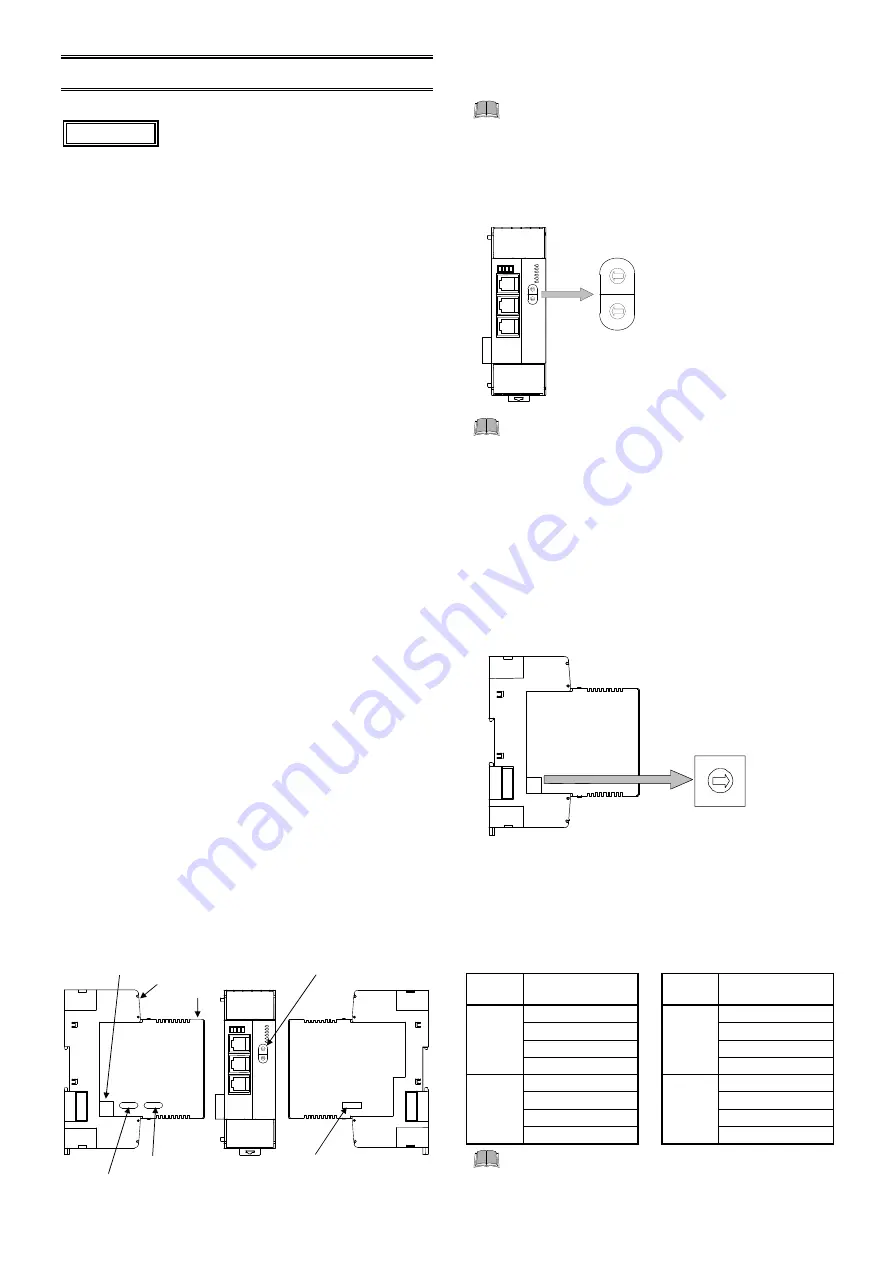
4.1 Address Setting
Set an address. For this setting, use a small slotted screwdriver.
To avoid problems or malfunction, do not duplicate
an address on the same communication line.
Module address setting
When using two or more modules, set the desired address to
each module.
(Common to PLC communication and host communication)
High-order digit setting
(set value
10)
Setting range: 0 to 95
(Factory set value: 0)
Low-order digit setting
(set value
1)
Address setting switch 1 (for module address)
FAIL/RUN
RX/TX
EVENT1
EVENT2
EVENT3
EVENT4
5
4
3
2
1
0
9 8 7
6
5
5
4
3
2
1
0
9 8 7
6
5
5
4
3
2
1
0
9 8 7
6
5
5
4
3
2
1
0
9 8 7
6
5
Do not set address 96 to 99.
Otherwise, malfunction may result.
For Modbus, the value obtained by adding “1” to
the set address corresponds to the address used
for the actual program.
Set the module address such that it is different to
the other addresses on the same line. Otherwise,
problems or malfunction may result.
Unit address setting
When two or more X-TIO-R modules are multi-drop connected,
set an address to each X-TIO-R module. This becomes the unit
address of the SRX unit.
(Common to PLC communication/host communication)
Left side view
Setting range:
0 to 15 [0 to F: hexadecimal]
(Factory set value: 0)
9
8
7
C
B
A
6
5
4
3
2
1
0
F
E
D
Address setting switch 2
(for unit address)
PLC communication
Up to four X-TIO-R modules can be connected to a PLC
communication port. Therefore the unit address uses the four
X-TIO-R modules as a group. Use consecutive numbers in any
one of four groups in the following table as unit address.
Group
Address setting
switch 2
Group
Address setting
switch 2
Group 1
0
Group
3
8
1
9
2
A
3
B
Group 2
4
Group
4
C
5
D
6
E
7
F
Always set the unit address of each group including
0, 4, 8 or C. 0, 4, 8 or C becomes the master for
communication transfer.
CAUTION


