


IM100CZ08-E9
3
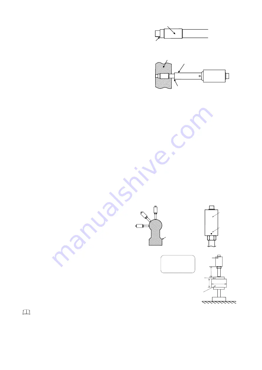
Mounting pressure sensors
•
When the diaphragm at the end of CZ-200P and its surroundings completely
touch with its mounting hole, large indication error may occur. In this case,
temperature may exert a large influence especially upon the zero point.
Therefore, much attention should be paid when a mounting hole is drilled.
•
When using a lead pipe cover (optional), pay attention that the lead pipe cover
end does not directly touch the barrel. (Refer to the
Exposed length at the
bottom of the sensor outer case
)
•
Prior to mounting the pressure sensor, check the appearance of the diaphragm. If the diaphragm has a deformed or abnormal end, it needs to
be repaired or re-calibrated. As there is a case where the diaphragm is already deformed when used previously, carefully check its condition
before the pressure sensor is re-used.
Mounting hole
•
When mounting the pressure sensor, check its mounting hole dimensions. (Do not over tighten its screw.
)
•
If resin or its carbide still remains in the mounting hole, this may damage the pressure sensor. Therefore, prior to mounting the sensor, always
remove any residue from the mounting hole.
•
Check that the diaphragm surface does not protrude from the inner wall of the barrel, since this may score the diaphragm surface with the
screw, etc. If necessary, adjust the position between the diaphragm surface and the inner wall of the barrel using stainless steel packings, etc.
•
For the loose nut type, resin leakage may occur more easily than the fixed nut type, as the pressure sealing surface becomes wider. If any
resin leaks through the mounting gap of the sensor, use copper packings (thickness: t
=
2 mm) or aluminum packings (thickness: t
=
2 mm) by
taking into account the position between the diaphragm surface and the inner wall of the barrel. (Copper Packing: Included in only the Loose
nut type)
Mounting direction
•
If the sensor is installed in the upright direction (Fig.1-A), it may be affected directly by heat flow from heater or heat source (rising current of
heated air). In such a case, the temperature of the strain gauge in the sensor may exceed an allowable maximum temperature of 200
°
C. In
order not to exceed this limit temperature, it is necessary to keep the sensor outer cylinder surface at a temperature of less than 180
°
C
(Fig.2). Conduct the following treatments.
1.
In order to avoid heat flow, wind a heat insulating material round such a heat source (heater, etc.).
2.
Further extend the length of the exposed lead pipe.
•
In order to keep the specified sensor performance longer, it is recommended that the sensor outer cylinder surface temperature be keep at
less than 180
°
C.
•
When the sensor is installed in the upright position, thermal effects on the sensor may not sufficiently lessen even if the length of the exposed
lead pipe is further extended. In this case, take measures of
1
.
•
The effect of heat flow lessens as the installing direction of the
sensor changes from the slanting direction (Fig.1-B) to the
horizontal direction (Fig.1-C) in this order. In this case, take
measures of
1
and
2
if necessary by checking the sensor outer
cylinder surface temperature.
(To the relevant manufacturer: It is recommended that the sensor
be installed in the horizontal or slanting direction in order to lessen
the effect of heat on the strain gauge.)
Exposed length at the bottom of the sensor outer case
•
Cases where the temperature of the strain gauge in the sensor become less
than 150
°
C is as follows:
−
The effect of heat flow is small.
−
The sensor is installed in the upright position.
−
The diaphragm is at a temperature of 400
°
C.
−
The length of the exposed sensor outer cylinder is more than 70 mm.
(Refer to Fig. at the right)
However, as the effect of heat flow from an actual extruder is serious, if there is
no enough exposed section below the sensor outer cylinder even at a diaphragm
temperature of less than 200
°
C, the operating temperature of the sensor strain
gauge may exceed its limit. Therefore, check the temperature environment where
the sensor is installed (by indirectly checking the temperature of the sensor outer
cylinder surface), and take necessary measures to lessen the temperature of the
sensor strain gauge by using a heat insulating material, if necessary.
If the temperature of the sensor outer cylinder surface exceeds 160
°
C, the outer cylinder surface changes its color from black to dark
brown and then brown in this order. If it exceeds 180
°
C, the color may change to silver.
•
A lead pipe cover (optional) is mainly for protecting the exposed section below the sensor outer cylinder from being exposed to cold wind.
Therefore, do not install the sensor such that it is embedded in the heat source (such as in the barrel or heater) together with the lead pipe cover.
This may heighten thermal conductivity from the heat source, resulting in a temperature increase in the sensor strain gauge.
Handling of cable
To prevent damage to the wire inside, do not bend the flexible jacketed cable or the flexible tube for the thermocouple less than the bending
radius (it should not be shorter than the fixed length) or forcibly pull or twist when handling.
Do not wind sealing tapes, etc. round this section
for preventing oil or resin leakage.
Packing surface (Sealing surface)
[Flat tightening or tapered tightening surface]
(Oil or resin leakage is prevented at this point.)
Barrel
Lead pipe cover (optional)
Mount the sensor so that this block
does not directly touch the barrel
.
The aims of
a temperature
measurement
position
(Fig. 2)
(Fig. 1)
A: Upper mounting
B: Oblique mounting
C: Side mounting
A section of a extruder
A
B
C
Outer cylinder
Mounting environment:
Ambient temperatures
at room temperatures
25
°
C
CZ-200P
Mounting adapter
Temperature of heater
400
°
C
φ
90
60
70
Unit: mm