background image

ENGLISH

69

1 Front panel

2 Fire door

3 Fire door glass

4 Ash drawer

5 Automatic mechanism for fire 

door closure

6 Ash shaker lever

7 Vain/Leaf

8 Vermiculite

9 Grill

10 Flame keeper

11 Side

12 Primary air lever

13 Plinth

14 Flue outlet

15 Oven door

16 Oven door lever

17 Oven door glass

18 Thermometer

19 Baking pan

20 Basement

Together with Rizzoli stoves you will find some ac-

cessories that simplify the installation, the mainte-

nance and the daily use of the device.

• Instruction booklet

• Green booklet and certificate of warranty

   for the stove

• Ash drawer

• Scraper

• Baking pan (X Chef Range)

• Devices for the connection of the stove

   to the chimney hood

• Sponge for cleaning the fire door glass

• Tar blocking device (X BasicX PlusX Vision

   Range); ref. chapter 4.8

1.6 ACCESSORIES

The stove must be installed by experienced people 

according to the specific technical laws. In particu-

lar it is important to pay attention to the chimney, 

which must be suited and dimensioned according 

to the device. When placing the stove, you must 

pay  attention  to  prevent  damages.  Do  not  drag 

the  stove,  move  it  always  keeping  it  lifted  from 

the floor. Do not lift the stove by handles. If there 

is furniture near the stove, be sure the minimum 

safety distances in case of inflammable or sensible 

to  high  temperatures  materials  according  to  the 

technical data (see paragraph 6.5). 

In case of floor made of inflammable materials it 

is necessary to put a fire-proof protection on the 

floor in front of the fire door. The protection must 

extend for a minimum of 80 cm in front  and for 

a minimum of 30 cm sideways over the fire door. 

The device must be placed on a floor with enough 

load capacity. If the existing building does not sat-

isfy this condition, you must adopt different solu-

tions (for example you can use a plate to distribute 

the load). During the installation it must be consid-

ered the stability of the device. If necessary, it is 

possible to regulate the levelling pins to level the 

device (see picture 2).

To  improve  the  stability  it  is  possible  to  fix  the 

stove to the floor with silicon or with two screws 

placed in the rear part of the stove itself.

To  fix  the  stove  to  the  floor with  the  screws,  to 

work in the easiest way it is suggested to unfix the 

rear covering of the stove (see chapter 2.10).

2.1 

GENERAL NOTES

2.2 PLACEMENT

INSTALLATION

2

Summary of Contents for X Art Basic

Page 1: ...Istruzioni d uso Gebrauchsanweisung Instructions Manuel d utilisation ...

Page 2: ......

Page 3: ...ise 34 Montage 37 Gebrauch 51 Wartung 54 Was tun wenn 58 Technische daten 59 Garantie 61 ENGLISH Warnings 66 Installation 69 Use 83 Maintenance 86 What to do if 90 Technical data 91 Warranty 93 FRANÇAIS Avertissements 98 Installation 101 Utilisation 115 Entretien 118 Que faire si 122 Données techniques 123 Garantie 125 ...

Page 4: ...a Le prime accensioni della stufa e le prime ac censioni stagionali devono essere eseguite con fuoco moderato poco combustibile così ven gono evitati eventuali processi di assestamento e rotture delle parti interne Il caricamento di un quantitativo eccessivo di legna può provocare il surriscaldamento dell ap parecchio e danni a cose e persone Prima di allontanarvi per lungo tempo accertate vi che ...

Page 5: ...5 33 cm e diametro 7 9 cm Materie plastiche legno trattato carta cartone rifiuti e in generale ogni materiale non previsto non possono essere utilizzati come combustibile La combustione di questi materiali è vietata dalle norme in vigore è dannosa per l ambiente per la stufa per la canna fumaria e anche per la vostra salute L apparecchio non può essere utilizzato come inceneritore Si raccomanda di...

Page 6: ... Basic X Plus X Vision X Chef Figura 1 1 5 COMPONENTI DELLA STUFA 2 2 3 3 4 4 5 5 9 9 8 8 10 10 20 7 6 6 14 14 11 11 12 12 21 13 1 2 2 3 3 4 4 5 5 9 9 8 8 10 10 19 21 21 13 13 18 16 17 15 14 14 7 7 6 6 12 12 11 11 ...

Page 7: ... precau zioni per evitare danneggiamenti Evitate di tra scinare la stufa ma spostatela sempre staccandola dal suolo La stufa non va spostata facendo forza sulle maniglie Nel caso siano presenti dei mobili nelle vicinanze accertatevi di mantenere le di stanze minime di sicurezza nel caso siano presenti materiali infiammabili o sensibili alle temperature secondo quanto previsto nei dati tecnici vedi...

Page 8: ...ura 2 5 figura 4 A questo punto si può regolare singolarmente ciascun piedino presente in prossimità degli angoli così da livellare in modo corretto la stufa Nelle stufe con finiture X Art e X Rock la regolazione dei piedini viene fatta acceden do dall esterno prima della fase di montaggio delle ceramiche figura 5 Per la regolazione dei piedini utilizzate una chiave misura 8 A Nr 8 B A Nr B Figura...

Page 9: ...ITALIANO 7 A Nr 2 5 x4 x4 Nr 8 Nr 8 B A Nr 2 5 x4 x4 Nr 8 Nr 8 B Figura 4 Regolazione dei piedini apparecchi con finitura X Line Figura 5 Regolazione dei piedini apparecchi con finiture X Art e X Rock ...

Page 10: ...i materiale purché adatto e purché il camino sia ben isolato Consultate un tecnico specializzato oppure lo spazzacamino responsabile di zona per qualsiasi problematica riguardante camino canna fumaria e raccordo con la stufa A B C D E H Figura 6 Le parti componenti del camino A Stufa B raccordo o canale da fumo C Canna fumaria D Comignolo E Zona di riflusso Il camino nel suo insieme deve essere di...

Page 11: ...assima per il dimensionamento della canna fumaria in funzione della altezza della canna fumaria A B C D E H ø imbocco ø canna fumaria H 4m ø canna fumaria 4m H 6m ø canna fumaria H 6m Depressione necessaria 150 mm Tiraggio non garantito 160 mm 150 mm 12 Pa Modello Serie X La canna fumaria deve essere ben isolata e preferi bilmente a sezione circolare La canna fumaria non deve presentare difetti re...

Page 12: ... stufe a legna serie X vengono fornite di serie con l uscita fumi superiore I modelli serie X Basic e XVision hanno la predispo sizione anche per l uscita fumi posteriore Per i modelli X Plus e X Chef l unica uscita fumi pos sibile è solo superiore Sui modelli serie X Plus è possibile inserire su ri chiesta degli anelli accumulatori in materiale re frattario in modo da garantire un lento rilascio ...

Page 13: ...e apparecchi con finiture X Art e X Rock 1 2 1 2 Nr 6 1 2 Sui modelli serie X Basic e X Vision è possibile mo dificare l uscita fumi da superiore a posteriore Per fare questo occorre innanzitutto togliere il cappel lo della stufa e smontare il rivestimento posteriore Nel caso di finiture X Art e X Rock si devono to gliere due viti di fissaggio del rivestimento stesso vedi figura 12 ...

Page 14: ...to che la sua funzione è quella di fermare eventuali blocchi di catrame nel caso di camini diritti e sen za eventuali punti di raccolta cenere vedi capitolo 4 8 fig 25 Una volta completata questa operazione si dovrà riposizionare il rivestimento posteriore togliendo il tappo di chiusura ed infine il cappello a cui si dovrà aggiungere il tappo fornito in dotazione con l apparecchio ATTENZIONE Verif...

Page 15: ... del rivesti mento dei fianchi Su ciascun fianco deve essere montata ad incastro prima la parte inferiore e poi quella superiore Nelle stufe con finitura X Art le ceramiche da inserire per prime sono quelle poste dietro ad angolo Alla fine si dovrà montare corret tamente il cappello della stufa insieme alla lamiera per l uscita fumi superiore Se il montaggio dovesse risultare difficoltoso è con si...

Page 16: ...necessario chiudere la canna fumaria al di sotto del tubo di raccordo con del materiale ignifugo Il raccordo con il camino deve essere fissato bene e sigillato non deve presentare restringimenti e non deve andare a diminuire la sezione utile del cami no vedi figura 15 Nel caso in cui nelle vicinanze sia presente del materiale infiammabile o sensibile alle temperature il raccordo va isolato opportu...

Page 17: ...ne di cappe aspiranti di camini o di sfiati La presa d aria del locale deve avere una superficie minima di 80 cm Su richiesta Rizzoli può fornire delle valvole studiate appositamente per permet tere l apertura automatica della presa d aria solo quando necessario per il funzionamento della stu fa a legna in modo da garantire una depressione massima di 4 Pa nel locale di installazione La stufa a leg...

Page 18: ...r rispondenza della stufa oppure a parete attraverso la parte posteriore vedi tabella 2 e figura 18 Figura 18 Vista posteriore e inferiore della stufa a legna e specifiche per il collegamento con la presa d aria esterna C A B E F H Tabella 2 Misure per collegamento presa aria esterna Misure in mm X Basic X Plus X Chef X Vision X Basic X Plus X Chef X Vision 95 95 95 120 120 120 230 210 210 210 83 ...

Page 19: ...ntilatori di estrazione di aria del locale potrebbero causare problemi per il corretto funzionamento dell apparecchio in mancanza di apposita presa d aria o in caso di presa d aria sottodimensionata 2 14 SPORTELLO VANO LEGNA OPTIONAL Sulle stufe serie X Basic X Plus e X Chef è possibile mettere su richiesta uno sportello dotato di chiu sura assistita in modo da nascondere alla vista il vano porta ...

Page 20: ...stibile Nelle prime accensioni si potrebbero formare degli odori dovuti a residui di lavorazione Questo feno meno è normale richiede la ventilazione del locale e scomparirà in breve tempo Tutto il materiale refrattario presente nella stufa subisce un processo di assestamento a causa del quale si possono creare piccole fessure o crepe questi fenomeni non pregiudicano in alcun modo il funzionamento ...

Page 21: ...uò essere mantenuta effettuando un altra carica e così via Il mantenimento della combustione nel tempo è ga rantito dal corretto funzionamento del camino il qua le permette di evacuare i fumi e contemporaneamen te di far alimentare la fiamma con l aria comburente In questo modo le caratteristiche realizzative del ca mino influiscono in modo determinante sul corretto funzionamento della stufa a leg...

Page 22: ...siglia di seguire le indicazioni per le regolazioni dell aria riportate nella tabella 3 Una volta ottenuto il letto di braci per introdurre il combustibile all interno della camera di combu stione si deve aprire leggermente la porta fuoco di alcuni centimetri e per alcuni secondi in modo da permettere alla differenza di pressione di assestar si prima di aprire interamente la porta fuoco A questo p...

Page 23: ...emperatura con l aggiunta di circa 1 Kg di legna ogni carica fino al raggiungimen to delle braci Una volta che la temperatura nel forno diventa stabile inserire la teglia con i biscotti nella po sizione centrale del forno per 10 minuti poi estrarre la teglia girarla e reinserirla sempre nella posizione centrale per altri 5 minuti Infine togliere la teglia dal forno e lasciare raffreddare i biscott...

Page 24: ...ivamente a stufa fredda utiliz zando un panno morbido ed asciutto e gli appositi prodotti in commercio Per le parti verniciate evitate l uso di abrasivi e di detersivi aggressivi o acidi Si raccomanda anche di non utilizzare solventi o alcol denaturato sulle parti verniciate Tutte le volte che si utilizza la stufa occorre prima pulire la graticola porta legna almeno dai depositi più grossolani Per...

Page 25: ...ccolo e maneggevo le in modo da poter accedere nel modo migliore all interno dell apparecchio Per fare questo occor re smontare il raccordo con il camino e successiva mente procedere con la pulizia dall alto Nella serie X Chef per consentire una rimozione dei residui di combustione anche nella zona sotto il forno è presente un pianale mobile Per proce dere alla pulizia si deve aprire completamente...

Page 26: ...zione di fermare preventivamente i blocchi di catrame durante la pulizia della canna fumaria in modo da preservare la stufa al suo interno figura 25 Questo disposi tivo è utile nel caso di camini diritti senza nessun punto di raccolta cenere In concomitanza con la pulitura del camino pro cedete comunque anche alla pulizia interna della stufa pulendo i giri fumo Dopo la pulizia del cami no accertat...

Page 27: ...altrimenti si potrebbero causare delle deformazioni e anche delle rotture Per questo vanno tenuti liberi e puliti gli spazi che permettono la dilatazione sia all interno che all e sterno della stufa Gran parte dei componenti della stufa sono fa cilmente smontabili con un semplice cacciavite eventuali riparazioni o modifiche saranno più ve loci ed economiche se il pezzo interessato viene recapitato...

Page 28: ... ci siano perdite nella canna fumaria e nei raccordi Verificare che non ci siano altri apparecchi col legati alla stessa canna fumaria Verificare che il camino non prosegua sotto il raccordo della stufa Verificare che il comignolo sia adatto alla ubicazione in cui si trova in zone ventose può essere necessario predisporre un comignolo anti vento Verificare che il combustibile sia adatto secco e di...

Page 29: ... Pa 195 C 5 3 g s 2 0 kg h 3 0 kg 45 min 245 kg 7 7 kW 87 1 0 055 12 Pa 195 C 5 3 g s 2 0 kg h 3 0 kg 45 min 294 kg 7 7 kW 87 1 0 055 12 Pa 195 C 5 3 g s 2 0 kg h 3 0 kg 45 min 126 kg 7 7 kW 87 1 0 055 12 Pa 195 C 5 3 g s 2 0 kg h 3 0 kg 45 min Modello X Plus X Basic X Chef X Vision Per apparecchi a potenza nominale inferiore a 8 kW non è richiesta la prova a potenza ridotta Vereinbarung Art 15a B...

Page 30: ...lle Serie X 20 cm 10 cm 120 cm cm 6 5 DISTANZE DI SICUREZZA Modello Lateralmente Dietro Davanti Sopra Distanze di sicurezza da materiale infiammabile o sensibile al calore in assenza di sistemi di isolamento aggiuntivi 6 6 REGOLAZIONI ALLA POTENZA NOMINALE Regolazione aria primaria Aperta a metà Modello Serie X Potenza nominale Rendimento Emissioni CO 13 O2 Emissioni polveri 13 O2 Idoneo secondo B...

Page 31: ...li il cliente è tenuto a versare le spese di trasporto Eventuali vizi o errori nei materiali devono essere segnalati entro 8 giorni dal ricevimento della mer ce e in ogni caso non implicano che il solo obbli go alla sostituzione di quanto fornito escludendo qualsiasi responsabilità ulteriore Sono escluse dalla garanzia Le parti difettose a causa di negligenze e trascu ratezze nell uso Le parti dif...

Page 32: ...e nazionale o locale o indicate nel presente libretto d istruzioni Per qualsiasi controversia o contestazione sarà com petente sempre e solo il foro di Bolzano 7 7 RESPONSABILITÀ 7 8 TRIBUNALE COMPETENTE Rizzoli S r l è costantemente impegnata nel migliorare i propri prodotti per questo il contenuto del presente libretto di istruzioni può cambiare senza preavviso Avvertenza ...

Page 33: ...l punto 8 Si rilascia la presente dichiarazione sotto la responsabilità esclusiva del fabbricante di cui al punto 4 Emissioni prodotti della combustione Rendimento 8 Prestazione dichiarata Caratteristiche essenziali Specifica tecnica armonizzata Resistenza al fuoco 5 Nome e indirizzo del mandatario 3 Usi previsti del prodotto conformemente alla relativa specifica tecnica armonizzata 6 Sistema di v...

Page 34: ... fumi posteriore Serie X Basic X Vision pag 11 2 11 Montaggio fianchi finiture X Art X rock pag 13 2 12 Corretto allacciamento al camino pag 14 2 13 Presa d aria pag 15 2 14 Sportello vano legna optional pag 17 2 15 Prima accensione pag 18 2 16 Assestamenti pag 18 3 USO pag 19 3 1 Funzionamento pag 19 3 2 Accensione pag 19 3 3 Regolazione dell aria pag 20 3 4 Cottura nel forno Serie X Chef pag 21 ...

Page 35: ... 6 4 Emissioni secondo certificazione ambientale pag 28 6 5 Distanze di sicurezza pag 28 6 6 Regolazioni alla potenza nominale pag 28 7 GARANZIA pag 29 7 1 Dichiarazione di costruzione a regola d arte pag 29 7 2 Clausole generali pag 29 7 3 Modalità di garanzia pag 29 7 4 Vizi o errori nei materiali pag 29 7 5 Parti non incluse in garanzia pag 29 7 6 Prestazioni fuori garanzia pag 29 7 7 Responsab...

Page 36: ...zen Nachlegen und während der Aschekasten geleert wird Die Feuerraumtür darf während der Kaminofen in Betrieb ist und das Feuer brennt nicht geöff net werden Bei der ersten Inbetriebnahme des Kaminofens oder bei Beginn der Heizsaison darf das Feuer nicht zu stark sein wenig Brennstoff um even tuelle Rissbildungen und Beschädigungen inter ner Teile zu vermeiden Eine übermäßig hohe Holzbeladung kann...

Page 37: ...e Verbrennung dieser Stoffe ist laut geltenden Vorschriften untersagt da sie schädlich für die Umwelt den Kaminofen den Rauchabzug und auch für Ihre Gesundheit sind Ihr Kaminofen ist keine Müllverbrennungsanlage Verwenden Sie ausschließlich die empfohlenen Brennstoffe Auch flüssige Brennstoffe dürfen nicht verwendet werden 1 3 EMPFOHLENER BRENNSTOFF 1 4 ANDERE BRENNSTOFFE normalem Betrieb alle sec...

Page 38: ... X Basic X Plus X Vision X Chef Abb 1 1 5 KAMINOFEN BESTANDTEILE 2 2 3 3 4 4 5 5 9 9 8 8 10 10 20 7 6 6 14 14 11 11 12 12 21 13 1 2 2 3 3 4 4 5 5 9 9 8 8 10 10 19 21 21 13 13 18 16 17 15 14 14 7 7 6 6 12 12 11 11 ...

Page 39: ...et sein muss Für die Positionierung müs sen einige Vorsichtsmaßnahmen zur Vermeidung von Schäden eingehalten werden Den Kamino fen bei Standortveränderung nicht verschieben sondern anheben und verstellen Beim Anheben nicht an den Griffen halten Wenn sich in unmit telbarer Nähe Möbel leicht entflammbare oder wärmeempfindliche Materialien befinden muss die Einhaltung der vorgesehenen Mindestsicher h...

Page 40: ...zu können Abb 4 Nun können die Stellfü ße in den vier Ecken einzeln reguliert werden wodurch eine gleichmäßige Nivellierung erreicht werden kann Bei Kaminöfen in den Ausführungen X Art und X Rock gelangt man von außen bevor man die Verkleidung anbringt zu den Stellfüßen Abb 5 Zur Regulierung der Stellfüße wird ein Schlüssel Nr 8 benötigt A Nr 8 B A Nr B Abb 2 Fixierung des Kaminofens mittels Silik...

Page 41: ...UTSCH 39 A Nr 2 5 x4 x4 Nr 8 Nr 8 B A Nr 2 5 x4 x4 Nr 8 Nr 8 B Abb 4 Regulierung der Stellfüße Kaminofen in der Ausführung X Line Abb 5 Regulierung der Stellfüße Kaminöfen in den Ausführungen X Art X Rock ...

Page 42: ...echen vorgeschrie ben Die Art der Werkstoffe spielt eine untergeord nete Rolle sofern sie geeignet sind und der Rauch abzug gut isoliert ist Für jegliche Problematik bezüglich Schornstein Rauchabzug und Anschlussstutzen kontaktieren Sie einen spezialisierten Techniker oder den zuständi gen Schornsteinfeger A B C D E H Abb 6 Teile des Kamins A Kaminofen B Rauchrohrstutzen C Rauchabzug D Schornstein...

Page 43: ...die richtige und falsche Ausführung des Rauchabzugs Abb 8 Maß H für Bemessung des Rauchabzugsrohrs Tabelle 1 Grundsätzliche Angaben zur Bemessung des Rau chabzugs je nach Höhe des Rauchabzugsrohrs A B C D E H ø Rauchausgang ø Rauchabzug H 4m ø Rauchabzug 4m H 6m ø Rauchabzug H 6m Empfohlener Förderdruck 150 mm Rauchzug nicht gewährleistet 160 mm 150 mm 12 Pa Modell Serie X Das Rauchabzugsrohr muss...

Page 44: ...en und dem Rauch abzug muss festsitzen und gut abgedichtet sein Kaminöfen der Serie X werden serienmäßig mit Rauchausgang oben geliefert Die Modelle der Serie X Basic und X Vision haben auch eine Anschlussmöglichkeit auf der Rückseite Die Modelle X Plus und X Chef hingegen können nur oben angeschlossen werden Für Modelle der Serie X Plus sind auf Anfrage wär mespeichernde Ringe erhältlich die eine...

Page 45: ...leidung Kaminöfen in den Ausführungen X Art X Rock 1 2 1 2 Nr 6 1 2 Die Modelle der Serie X Basic und X Vision kön nen anstatt oben auf der Rückseite angeschlos sen werden Dafür muss das Top entfernt und die hintere Verkleidung abmontiert werden Bei den Ausführungen X Art und X Rock müssen auch die beiden Fixierungsschrauben der Verkleidung ent fernt werden siehe Abb 12 ...

Page 46: ...habzug der keine Stellen aufweist an denen sich Ruß an sammeln kann eventuell vorhandene Teerblöcke aufhalten siehe Kapitel 4 8 Abb 25 Sobald dieser Umbau erfolgt ist kann die Verklei dung auf der Rückseite wieder montiert werden nachdem der Deckel entfernt worden ist Schluss endlich kann das Top wieder angebracht werden Im Lieferumfang ist ein Deckel für das Top enthalten ACHTUNG Überprüfen Sie d...

Page 47: ...t werden auf jeder Seite werden die Seitenwände eingehängt zuerst die Unterseite und dann erst die obere Seite Bei Modellen in der Ausführung X Art muss zu allererst die hintere Ke ramikverkleidung im Eck angebracht werden Zum Schluss muss man das Top vom Kaminofen zusam men mit der Vorrichtung für den Rauchausgang ordnungsgemäß anbringen Bei Montageproble men die Halterungsschrauben auf der Verkl...

Page 48: ...es unterhalb des Anschlussstutzens mit feuerfestem Material zu verschließen Der Anschluss zwischen Kaminofen und Rauchabzug muss festsitzen und gut abgedichtet sein sowie keine Verengungen oder Querschnittreduzierung am Schornstein aufweisen siehe Abb 15 Falls sich in nächster Nähe entzündliche oder wärme empfindliche Materialien befinden muss eine pas sende Isolierung vorgenommen sowie ein entspr...

Page 49: ...Kamine oder Entlüftungsanlagen darin befinden Die Lüftungsklappe des Raumes muss eine Min destfläche von 80 cm aufweisen Auf Anfrage liefert Rizzoli eigens hierzu entwickelte Lüftungs klappen die sich nur während des Betriebes des Kaminofens automatisch öffnen um einen maxi malen Unterdruck von 4 Pa im Aufstellungsraum zu garantieren Der Kaminofen ist auch für den direkten Anschluss an einen exter...

Page 50: ...hluftzufuhr entweder über den Boden unter dem Kaminofen oder auf der Rückwand hinter dem Kaminofen laut Tabelle 2 Abb 18 Rück und Unteransicht des Kaminofens und Angaben für den Anschluss an die externe Frischluftzufuhr C A B E F H Tabelle 2 Maße für den Frischluftzufuhr Anschluss Maße in mm X Basic X Plus X Chef X Vision X Basic X Plus X Chef X Vision 95 95 95 120 120 120 230 210 210 210 83 83 83...

Page 51: ...usgezogen wird ACHTUNG Dunstabzugshauben oder Lüftungsanlagen im Aufstellungsraum können ebenfalls die Funktionstüchtigkeit des Kaminofens bei fehlender eigens dafür vorgese hener Frischluftklappe oder bei unterdimensionierter Frischluftzufuhr beeinträchtigen 2 14 GESCHLOSSENE HOLZAUFBEWAHRUNG OPTIONAL Modelle der Serie X Basic X Plus und X Chef kön nen auf Anfrage mit einer Holzaufbewahrung mit s...

Page 52: ...gres siv erhöht werden Beim ersten Anheizen können aufgrund von Verarbeitungsrückständen Gerüche entstehen Diese Geruchbildung ist normal und verschwindet nach einiger Zeit Aufstellraum ein fach gut durchlüften Das vorhandene Schamottmaterial im Inneren des Kaminofens ist einem natürlichen Setzungspro zess ausgesetzt wodurch kleine Risse und Sprün ge entstehen können die jedoch keinesfalls die Fun...

Page 53: ...te Aufrechterhaltung der Verbren nung kann nur dann garantiert werden wenn der Rauchabzug einwandfrei funktioniert d h die Rauchgase abzieht und gleichzeitig die Flamme durch Zuführung von Verbrennungsluft speist Auf diese Weise haben die Bau Charakteristiken des Rauchabzugs bedeutenden Einfluss auf die ein wandfreie Funktionstüchtigkeit des Kaminofens Die Verbrennung von Holz erfordert dass die L...

Page 54: ... geschlossenem externen Frischluftkanal wichtig Für eine gute Funktionstüchtigkeit des Kamino fens wird generell empfohlen die Anweisungen zur Luftregulierung in Tabelle 3 zu befolgen Sobald ein Glutbett erreicht wird muss vor der kompletten Öffnung der Feuerraumtür zum Ein legen von weiterem Brennstoff in die Brennkam mer die Feuerraumtür für ein paar Sekunden leicht geöffnet werden ein paar cm u...

Page 55: ...chen der Glut aufgelegt wird Nachdem im Backofen eine stabile Temperatur erreicht wurde das Backblech mit den Keksen in der Mitte einschieben und 10 Minuten ba cken dann herausnehmen komplett drehen wieder in der Mitte einschieben und für weitere 5 Minuten backen Zum Schluss Backblech herausnehmen und die Kekse abkühlen lassen Die Menge an Glut darf nicht übermäßig sein da ansonsten die Rauchgaste...

Page 56: ...leifmittel scheuernde aggressive oder säure haltige Reinigungsmittel verwenden Verwenden Sie auf keinen Fall Lösungsmittel oder Spiritus um lackierte Teile zu reinigen Vor jedem Gebrauch des Kaminofens muss der Schüttelrost zumindest von den gröbsten Rück ständen befreit werden Dazu muss der entspre chende Griff herausgezogen werden Abb 22 damit die Asche vom Rost in den darunterliegen den Ascheka...

Page 57: ... durch das Entfernen von Asche und Rußrückständen die sich während dem Gebrauch ablagern Hierzu ist es ratsam ei nen handlichen Staubsauger mit einem geeigneten Aufsatz mit dem man in alle Zwischenräume des Kaminofens gelangt zu verwenden Für die Reini gung entfernt man den Anschlussstutzen und be ginnt mit der Reinigung folglich von oben Für die Kaminöfen der Serie X Chef damit Rück stände auch u...

Page 58: ...ng vorhanden die bei der Reinigung des Rauchabzugs eventuell vorhandene Teerblö cke aufhält und den Kaminofen schützt Abb 25 Diese Vorrichtung wird benötigt wenn der Rauch abzug gerade ist und keine Stellen aufweist an denen sich Ruß ansammeln kann Gleichzeitig mit der Schornsteinreinigung sollte auch eine Innenreinigung des Kaminofens sowie die Reinigung der Rauchgaszüge vorgenommen werden Nach e...

Page 59: ...könnte Verformungsschäden und Rissbildungen hervorrufen Achten sie deshalb darauf dass sowohl die externen wie auch inter nen Dehnungsfugen des Kaminofens stets frei von Schmutz und gereinigt sind Ein Großteil der Kaminofen Bestandteile kann problemlos mit einem normalen Schraubenzieher abmontiert werden Eventuelle Reparaturen oder Änderungen sind schneller und preiswerter wenn die entsprechenden ...

Page 60: ...n in Betrieb sind Die richtige Bemessung des Schornsteines und des Anschlusses kontrollie ren Kontrollieren ob der Schornstein nicht verstopft oder kürzlich gereinigt wurde Über prüfen ob das Abzugsrohr und die Anschlüsse dicht sind Kontrollieren ob der Rauchabzug nicht bis unter den Kaminofen reicht Den richtigen Standort des Schornsteinaufsatzes überprüfen in windreichen Gegenden kann ein entspr...

Page 61: ... 0 kg 45 min 245 kg 7 7 kW 87 1 0 055 12 Pa 195 C 5 3 g s 2 0 kg h 3 0 kg 45 min 294 kg 7 7 kW 87 1 0 055 12 Pa 195 C 5 3 g s 2 0 kg h 3 0 kg 45 min 126 kg 7 7 kW 87 1 0 055 12 Pa 195 C 5 3 g s 2 0 kg h 3 0 kg 45 min Modell X Plus X Basic X Chef X Vision Die Prüfung mit reduzierter Nennwärmeleistung ist für Geräte mit einer Nennwärmeleistung unter 8 kW nicht erforderlich Vereinbarung Art 15a B VG ...

Page 62: ... Sterne Serie X 20 cm 10 cm 120 cm cm 6 5 SICHERHEITSABSTÄNDE Modell Seitlich Hinten Vorne Oben Sicherheitsabstände zu leicht entflammbaren oder temperaturempfindlichen Materialien ohne zusätzli che Isoliersysteme 6 6 EINSTELLUNGEN NENNWÄRMELEISTUNG Primärluft Regulierung Zur Hälfte geöffnet Modell Serie X Nennwärmeleistung Wirkungsgrad CO Emission 13 O2 Feinstaubemission 13 O2 Erfüllt die Anf der...

Page 63: ...Kundendienstzentren der Firma Rizzoli gehen zu Lasten des Kunden Eventuelle Materialfehler oder mängel müssen in nerhalb 8 Tagen nach Erhalt der Ware beanstandet werden Die Firma Rizzoli leistet in jedem Fall nur Gewähr zum Austausch der im Lieferumfang an geführten Waren und übernimmt keine weiteren Verantwortungen Von der Garantie ausgeschlossen sind Defekte Teile aufgrund nachlässiger und unsac...

Page 64: ...ühren sind Für jegliche Streitfälle ist der Gerichtsstand Bozen zuständig allerdings behält sich die Firma Rizzoli das Recht vor auch einen anderen Gerichtsstand oder den Gerichtsstand des Käufers als zuständi gen Gerichtsstand auszuwählen 7 7 HAFTUNG 7 8 GERICHTSSTAND Die Firma Rizzoli GmbH ist stets um die Verbesserung seiner Erzeugnisse bemüht und behält sich deshalb das Recht vor eventuelle Än...

Page 65: ...ngserklärung ist allein der Hersteller siehe Punkt 4 Emission von Verbrennungsprodukten Wirkungsgrad 8 Erklärte Leistung Wesentliche Merkmale Harmonisierte technische Spezifikation Feuerbeständigkeit 5 Name und Adresse des Auftragnehmers 3 Vorgesehene Verwendung des Produkts in Übereinstimmung mit der geltenden harmonisierten technischen Spezifikation 6 System zur Bewertung und Überprüfung der Lei...

Page 66: ... 43 2 11 Montage der Seitenwände Ausführung X Art und X Rock S 45 2 12 Richtiger Anschluss an den Rauchabzug S 46 2 13 Frischluftzufuhr S 47 2 14 Geschlossene Holzaufbewahrung Optional S 49 2 15 Erste Inbetriebnahme S 50 2 16 Setzungserscheinungen S 50 3 GEBRAUCH S 51 3 1 Betrieb des Kaminofens S 51 3 2 Anheizen S 51 3 3 Luftregulierung S 52 3 4 Backen und Braten im Backofen Serie X Chef S 53 4 WA...

Page 67: ...V S 60 6 4 Emissionen laut Umweltklassifizierung S 60 6 5 Sicherheitsabstände S 60 6 6 Einstellungen Nennwärmeleistung S 60 7 GARANTIE S 61 7 1 Erklärung zur fachgerechten Konstruktion S 61 7 2 Allgemeine Klauseln S 61 7 3 Garantiebestimmungen S 61 7 4 Materialfehler oder Mängel S 61 7 5 Vom Garantieanspruch ausgeschlossene Teile S 61 7 6 Leistungen nach Ablauf der Garantie S 61 7 7 Haftung S 62 7...

Page 68: ...rst lightings of the stove and the first se asonal lightings must be done with temperate fire in order to prevent possible breakings of the internal parts The loading of an excessive amount of wood may overheat the device and generate damages to things or persons Before leaving the house for a long time be sure that the device is not working Check regularly the seals the carbon and ash re siduals ...

Page 69: ...melled or treated wood or carton must not be burned Using this materials is forbidden by law and causes serious damage not only to your health and environment but also to the stove and the chimney The device must not be used as inciner ator It is recommended to use only the suggested combustibles and not liquid combustibles 1 3 RECOMMENDED COMBUSTIBLES 1 4 OTHER COMBUSTIBLES WARNING Painted part o...

Page 70: ... X Basic X Plus X Vision X Chef Picture 1 1 5 PARTS OF THE STOVE 2 2 3 3 4 4 5 5 9 9 8 8 10 10 20 7 6 6 14 14 11 11 12 12 21 13 1 2 2 3 3 4 4 5 5 9 9 8 8 10 10 19 21 21 13 13 18 16 17 15 14 14 7 7 6 6 12 12 11 11 ...

Page 71: ...ot drag the stove move it always keeping it lifted from the floor Do not lift the stove by handles If there is furniture near the stove be sure the minimum safety distances in case of inflammable or sensible to high temperatures materials according to the technical data see paragraph 6 5 In case of floor made of inflammable materials it is necessary to put a fire proof protection on the floor in f...

Page 72: ...le to regulate singu larly each pin placed near the corners in order to level correctly the stove In the stoves with X Art and X Rock finishes the regulation of the pins can be done accessing from the external side before fixing the ceramics see picture 5 For the regulation of the pins use a key with di mension 8 A Nr 8 B A Nr B Picture 2 Fixing of the stove to the floor with silicon Picture 3 Fix...

Page 73: ...ENGLISH 71 A Nr 2 5 x4 x4 Nr 8 Nr 8 B A Nr 2 5 x4 x4 Nr 8 Nr 8 B Picture 4 Regulation of the pins devices with X Line finish Picture 5 Regulation of the pins devices with X Art and X Rock finishes ...

Page 74: ...imney sweeper for any problem dealing with the chim ney chimney hood and connection to the stove A B C D E H Picture 6 Components of the chimney A stove B conjunction C flue D chimney E reflow zone Chimney must be dimensioned in a correct way according to the type of stove it is connected with minding the environmental and general conditions of the place in which it is placed The section of the ch...

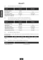
Page 75: ...mney according to its height A B C D E H ø entrance ø flue H 4m ø flue 4m H 6m ø flue H 6m Necessary depression 150 mm Draught not guaranteed 160 mm 150 mm 12 Pa Model Serie X The flue must be well isolated and circular if possi ble The flue must not have defects narrowings or losses All the inspection doors must be closed and well sealed The connection of other devices to the same chimney is not ...

Page 76: ...sealed X Range wood fired stoves are endowed with a standard upper flue outlet X Basic and X Vision models have also the predisposition for the rear flue outlet For X Plus and X Chef the flue outlet is only upper On X Plus Range models it is possible on demand to insert accumulation rings in refractory material in order to guarantee a slow release of heating also after the combustion is over For t...

Page 77: ...the rear covering X Art X Rock finishes devices 1 2 1 2 Nr 6 1 2 On X Basic and X Vision Range models it is possible to move the flue outlet from top to rear To do this remove the cap of the stove and unfix the rear co vering With X Art and X Rock finishes it is neces sary to remove two fixing screws of the covering itself see picture 12 ...

Page 78: ...an be removed assuming that its function is to block eventual pieces of tar in case of straight chimneys without ash collection points see chapter 4 8 picture 25 Once completed this operation the rear covering must be replaced removing the closing cap and finally the cap adding to it the cap given together with the device WARNING Check carefully that the gasket on the connector and on the cap does...

Page 79: ...essary to fix the covering of the sides On each side the lower part must be interlocked be fore the upper one On the stoves with X Art fin ish the first ceramics to be inserted are the ones placed behind cornered Finally it must be fixed the cap of the stove together with the steel sheet of the flue outlet If the fixing should be difficult it is suggested to release slightly the sustaining screws ...

Page 80: ...stove it may be necessary to close the conduct under the con nection pipe with fireproof materials The connection with the chimney must be always well fixed and sealed it must not have narrowing and must not decrease the usable section of the chimney see picture 15 If near the stove there is inflammable material or high temperatures sensi ble the connection must be isolated and the safe ty distanc...

Page 81: ... devices aspiring hoods chimneys and vent holes The air intake in the room must have a minimum surface of 80 cm2 On demand Rizzoli can give specific valves which can allow the automatic opening of the air intake only when it is necessary for the correct working of the stove in order to warrant a maximum depression of 4 Pa in the place of in stallation The wood fired stove can also be connected so ...

Page 82: ...spond ence with the stove or on the wall through the rear part of the stove see picture 18 and table 2 Picture 18 Rear lower sight of the stove and specifies for the connection with the air intake C A B E F H Table 2 Dimensions for the connection of the external air intake Dimensions in mm X Basic X Plus X Chef X Vision X Basic X Plus X Chef X Vision 95 95 95 120 120 120 230 210 210 210 83 83 83 8...

Page 83: ...ng it out towards yourself WARNING Aspiring hoods or extracting air fans in the room may generate problems to the device if there is not a suited air intake or in case of air intake sub dimensioned 2 14 WOOD VAIN LEAF OPTIONAL On X Basic X Plus and X Chef stoves it is possible to add on demand a leaf with assisted closure studied to hide the wood vain The installation of the wood vain leaf must be...

Page 84: ...small pieces In the next lightings you can pro gressively increase the load of combustible During the first lightings some smell due to pro cessing residuals might happen This phenomenon is normal it requires the ventilation of the room and will disappear quickly All the refractory materials inside the stove experi ence a settlement process that may generate small holes on the bricks such holes do...

Page 85: ...m bustible but it can be maintained lighted by making another load of combustible and so on The maintenance of the combustion in time is guaranteed by the correct working of the chimney which allows to evacuate the fumes and in the same time to feed the flame with oxidising air In this way the features of the chimney have a big influence on the correct working of the device The combustion of wood ...

Page 86: ... working of the device it is suggested to follow the instructions for air regula tions indicated in table 3 Once the layer of embers has created to insert the combustible inside the combustion chamber the fire door must be slightly open for few seconds to allow to the pressure difference to settle before opening completely the fire door Then insert n 2 wood chunks for a total weight of 2 kg taking...

Page 87: ...ding more or less 1 Kg of wood for every charge as the reaching of the coals Once the temperature becomes stable insert the baking pan with the biscuits in the central position in the oven for 10 minutes then extract the baking pan rotate it and reinsert it again in the cen tral position for other 5 minutes In the end remove the baking pan from the oven and leave cool the bi scuits The amount of e...

Page 88: ... suited products available on the mar ket For painted parts do not use abrasive or aggres sive solution It is also recommended to avoid the use of solvents or denatured alcohol on painted parts Every time you use the stove you have to clean the wood carrying grill before at least you have to clean the more rough deposits To do this it must be allowed the passage of the ash from the grill to the dr...

Page 89: ... cleaner with flexible handle and also terminal small and handy in order to access easily inside the device To do this it is necessary to unfix the chimney connection and then starting with the cleaning from the top In X Chef Range to allow the removal of combus tion deposits below the oven you have to remove a mobile panel to do this open completely the oven door remove the panel remove the depos...

Page 90: ...ocks the tar pieces eventually falling during the cleaning of the chimney hood in order to prevent damages inside the stove see picture 25 This de vice is useful in case of straight chimneys without ash collection points Together with the cleaning of the chimney make also the internal cleaning of the stove cleaning the fume circuits After the cleaning of the chimney be sure to have closed all the ...

Page 91: ...non must not be prevented otherwise deformations and breakings may occur For this reason the spaces that allow the dilatation both internal and external of the stove must be kept free and clean Most parts of the stove are easy to remove with a simple screwdriver eventual repairs or modifies will be faster if the concerned piece directly or by a dealer is sent to our factory The components in touch...

Page 92: ...that it was cleaned recently Ver ify that there are no losses in the exhaust pipe and in the conjunctions Verify that no other devices are connected to the flue Verify that the chimney does not go on under the wood fired stove Verify that the chimney suites the position in which it is situated in windy places you could have to install an anti wind chimney Verify that the combustible is right dry a...

Page 93: ... C 5 3 g s 2 0 kg h 3 0 kg 45 min 245 kg 7 7 kW 87 1 0 055 12 Pa 195 C 5 3 g s 2 0 kg h 3 0 kg 45 min 294 kg 7 7 kW 87 1 0 055 12 Pa 195 C 5 3 g s 2 0 kg h 3 0 kg 45 min 126 kg 7 7 kW 87 1 0 055 12 Pa 195 C 5 3 g s 2 0 kg h 3 0 kg 45 min Model X Plus X Basic X Chef X Vision For devices with nominal power lower than 8 kW it is not requested the test with reduced power Vereinbarung Art 15a B VG 31 1...

Page 94: ...mg m3 Model X Range 4 stars X Range 20 cm 10 cm 120 cm cm 6 5 SAFETY DISTANCES Model Laterally Behind From On Safety distances from inflammable or sensible to heat materials in absence of other isolating systems 6 6 REGULATIONS AT NOMINAL POWER Primary air regulation Half open Model X Range Nominal power Efficiency Emissions CO 13 O2 Dust emissions CO 13 O2 BimSchV suitability 7 7 kW 87 1 690 mg m...

Page 95: ...days since the customer receives the products and anyway this implies only the ob ligation to replace what provided excluding any additional responsibility This warranty does not cover the following and the customer will be required to pay repair charge even for defects occurring within the warranty pe riod referred to above Any defect that occurs due to mishandling Any defect that occurs due to o...

Page 96: ... and local law and of the instructions written in this booklet In case of controversy will be competent the law court of Bolzano only 7 7 NON RESPONSIBILITY DECLARATION 7 8 COMPETENT LAW COURT Rizzoli S r l is constantly working to improve its products for this reason the contents of this booklet may vary without notice Note ...

Page 97: ...e responsibility of the manufacturer identified in point 4 Emissions produced by combustion Efficiency 8 Declared performance Essential features Harmonized technical specification Fire resistance 5 Name and Address of the manufacturer 3 Intended use of the product in accordance with the relative harmonized technical specification 6 System of assessment and verification of constancy of performance ...

Page 98: ...ion pag 74 2 10 Rear flue outlet X Basic X Vision ranges pag 75 2 11 Sides fixing X Art and X Rock ranges pag 77 2 12 Correct conjunction to the chimney pag 78 2 13 Air intake pag 79 2 14 Wood vain leaf optional pag 81 2 15 First lighting pag 82 2 16 Settlements pag 82 3 USE pag 83 3 1 Operation pag 83 3 2 Lighting pag 83 3 3 Air regulation pag 84 3 4 Oven cooking X Chef range pag 85 4 MAINTENANCE...

Page 99: ...sions according to environmental certification pag 92 6 5 Safety distances pag 92 6 6 Regulations at nominal power pag 92 7 WARRANTY pag 93 7 1 Declaration of perfectly made product pag 93 7 2 General clauses pag 93 7 3 Warranty modalities pag 93 7 4 Imperfections or defects in the materials pag 93 7 5 Parts not included in warranty pag 93 7 6 Operations made out the warranty period pag 93 7 7 Non...

Page 100: ...flammes sont présentes Les premiers allumages du poêle ainsi que le premier allumage de chaque saison devront être effectués à feu modéré peu de combus tible afin d éviter d éventuels phénomènes de tassement et la rupture de pièces internes Le chargement d une quantité de bois excessive peut provoquer une surchauffe de l appareil pouvant entrainer une détérioration de l appa reil et d éventuelles ...

Page 101: ... matériaux non préconisés ne doivent jamais être utilisés comme combustible La combustion de ces matériaux est interdite par la réglementation en vigueur et est préjudiciable pour l environnement le poêle le conduit de cheminée et surtout pour votre santé L appareil ne doit pas être utilisé comme incinérateur Nous recommandons d utiliser exclusivement les combustibles recommandés et de ne pas util...

Page 102: ...0 X Basic X Plus X Vision X Chef Figure 1 1 5 COMPOSANTS DU POÊLE 2 2 3 3 4 4 5 5 9 9 8 8 10 10 20 7 6 6 14 14 11 11 12 12 21 13 1 2 2 3 3 4 4 5 5 9 9 8 8 10 10 19 21 21 13 13 18 16 17 15 14 14 7 7 6 6 12 12 11 11 ...

Page 103: ... l appareil Pour le positionnement vous devez res pecter certaines précautions pour éviter toute dé térioration Évitez de tirer le poêle et déplacez le en le soulevant du sol Ne déplacez pas le poêle en le saisissant par les poignées Si des meubles sont installés à proximité assurez vous de respec ter une distance minimale de sécurité en cas de présence de matériaux inflammables ou sensibles aux t...

Page 104: ...c une clé Allen taille 2 5 fi gure 4 Ensuite vous devez régler individuellement chaque pied situé dans les coins de manière à ni veler le poêle correctement Dans les poêles en fi nitions X Art et X Rock le réglage des pieds se fait par l extérieur avant le montage des céramiques figure 5 Pour le réglage des pieds utilisez une clé de taille 8 A Nr 8 B A Nr B Figure 2 Fixation du poêle avec du silic...

Page 105: ...FRANÇAIS 103 A Nr 2 5 x4 x4 Nr 8 Nr 8 B A Nr 2 5 x4 x4 Nr 8 Nr 8 B Figure 4 Réglage des pieds appareils en finition X Line Figure 5 Réglage des pieds appareils en finitions X Art et X Rock ...

Page 106: ... à condition qu il soit adapté et que le conduit de fumées soit correctement isolé Pour tout problème concernant le conduit de fumées le conduit de cheminée et le raccordement avec le poêle consultez un technicien spécialisé ou votre ramoneur A B C D E H Figure 6 Les composants du conduit de fumées A Poêle B Raccordement ou conduit de fumées C Conduit de cheminée D Mitre E Zone de reflux Dans son ...

Page 107: ...minée Tableau 1 Indications relatives au dimensionnement du conduit de cheminée en fonction de la hauteur du conduit de cheminée A B C D E H ø entrée ø conduit cheminée H 4 m ø conduit cheminée 4 m H 6 m ø conduit cheminée H 6 m Dépression nécessaire 150 mm Tirage non garanti 160 mm 150 mm 12 Pa Modèle Série X Le conduit de cheminée doit être correctement isolé et de préférence avec des sections r...

Page 108: ...Les poêles à bois de la série X sont fournis de série avec la sortie fumées située au dessus Les modèles des séries X Basic et X Vision sont prééquipés également pour une sortie fumées par l arrière Pour les modèles X Plus et X Chef la sortie fumées est possible uniquement par le dessus Sur les modèles de la série X Plus il est possible d intégrer sur demande des blocs accumulateurs dans un matéri...

Page 109: ...pareils en finitions X Art et X Rock 1 2 1 2 Nr 6 1 2 Sur les modèles des séries X Basic et X Vision il est possible de déplacer la sortie fumées du dessus vers l arrière Pour cela vous devez tout d abord retirer le chapeau du poêle et démonter le pan neau arrière Dans le cas des finitions X Art et X Rock vous devez retirer deux vis de fixation du panneau lui même voir figure 12 ...

Page 110: ...u qui sert à arrêter les éven tuelles obstructions de goudron dans les conduits de fumées droits et sans point de collecte des cendres peut être retiré voir par 4 8 fig 25 Une fois cette opération terminée repositionnez le panneau arrière en retirant le bouchon de fer meture puis le chapeau auquel il faudra ajouter le bouchon fourni avec l appareil ATTENTION Vérifiez attentivement que le joint pré...

Page 111: ...s panneaux latéraux Pour chaque côté vous devez d abord encastrer la partie inférieure puis la partie supérieure Dans les poêles en finition X Art les céramiques à insérer en premier sont celles situées à l arrière dans l angle Pour finir montez correcte ment le chapeau du poêle ainsi que la tôle pour la sortie fumées supérieure Si le montage s avère difficile nous conseillons de desserrer légèrem...

Page 112: ...r le conduit de che minée sous le tuyau de raccordement avec un ma tériau ignifuge Le raccord avec le conduit de fumées doit être correctement fixé et scellé il ne doit présenter aucun rétrécissement et ne doit pas réduire la sec tion utile du conduit de fumées voir figure 15 Si des matières inflammables ou sensibles aux tem pératures élevées sont présentes à proximité le raccord doit être isolé d...

Page 113: ...pirantes de conduits de fumées ou d évacuation La prise d air de la pièce devra avoir une surface minimale de 80 cm Sur demande Rizzoli peut fournir des clapets spécialement étudiés pour per mettre l ouverture automatique de la prise d air uniquement lorsque cela est nécessaire pour le fonctionnement du poêle à bois afin de garantir une dépression minimale de 4 Pa dans la pièce d installation Éven...

Page 114: ...u poêle ou au mur à travers la paroi postérieure voir tableau 2 et figure 18 Figure 18 Vue arrière et vue du dessous du poêle à bois et spécifications pour le raccordement avec la prise d air extérieur C A B E F H Tableau 2 Mesures pour le raccordement de la prise d air extérieur Dimensions en mm X Basic X Plus X Chef X Vision X Basic X Plus X Chef X Vision 95 95 95 120 120 120 230 210 210 210 83 ...

Page 115: ... Sans prise d air adaptée ou en cas de prise d air sous dimensionnée les hottes aspirantes ou les ventilateurs d extraction d air de la pièce pourraient entraver le bon fonctionnement de l appareil 2 14 PORTE NICHE À BOIS OPTION Sur les poêles des séries X Basic X Plus et X Chef il est possible sur demande d installer une porte do tée d une fermeture assistée de manière à cacher la niche à bois L ...

Page 116: ...us tible Lors des premiers allumages vous pourriez sentir des odeurs dues à des résidus d usinage Ce phé nomène est normal et nécessite une aération de la pièce Les odeurs disparaitront en peu de temps Le matériau réfractaire présent dans le poêle subit un processus de tassement pouvant provoquer de petites fissures ou craquelures Ces phénomènes ne compromettent aucunement le fonctionne ment du po...

Page 117: ...maintenue en rechar geant le poêle et ainsi de suite Le maintien de la combustion dans le temps est garanti par le bon fonctionnement du conduit de fumées qui permet d évacuer les fumées et en même temps d alimenter la flamme avec l air comburant De ce fait les caractéristiques de réa lisation du conduit de fumées influent de manière déterminante sur le bon fonctionnement du poêle à bois Afin d ob...

Page 118: ...conseillons de suivre les indications de régulation de l air fournies dans le tableau 3 Une fois que le lit de braises est formé pour intro duire le combustible dans la chambre de combus tion vous devez ouvrir la porte foyère de quelques centimètres pendant quelques secondes de ma nière à réduire la différence de pression avant d ouvrir complètement la porte foyère Introduisez ensuite 2 bûches de ...

Page 119: ...tant environ 1 kg de bois à chaque chargement jusqu à ce que les braises se for ment Une fois que la température du four est stable mettez au four au milieu la plaque avec les sablés pendant 10 minutes retirez la plaque retournez la et remettez la au four toujours au milieu pendant 5 minutes supplémentaires Sortez la plaque du four et laissez les sablés refroidir La quantité de braises ne doit pas...

Page 120: ... est froid à l aide d un chif fon doux et sec et des produits appropriés dispo nibles dans le commerce Évitez d utiliser des produits abrasifs et des dé tergents agressifs ou acides sur les parties peintes Nous recommandons également de ne pas utiliser de solvants ni d alcool dénaturé sur les parties peintes À chaque fois que vous utilisez le poêle vous devez préalablement nettoyer la grille à boi...

Page 121: ...spirateur avec un manche flexible et un embout petit et maniable de ma nière à pouvoir accéder correctement à l intérieur de l appareil Pour cela démontez le raccordement avec le conduit de fumées puis commencez le net toyage par le haut Dans la série X Chef pour permettre de retirer les résidus de combustion même dans la partie sous le four une plaque mobile est installée Pour le nettoyage ouvrez...

Page 122: ... de cheminée est installé à l intérieur du fourreau sur la sortie fumées supérieure afin de préserver l intérieur du poêle figure 25 Ce dis positif est utile dans le cas de conduits de fumées droits sans aucun point de collecte des cendres En plus du nettoyage du conduit de fumées effec tuez également le nettoyage intérieur du poêle en nettoyant le conduit des gaz Une fois le nettoyage du conduit ...

Page 123: ...ient apparaître Pour cela les espaces permettant la dilatation à l intérieur et à l extérieur du poêle ne doivent pas être obstrués et doivent être propres Une grande partie des composants du poêle est facilement démontable avec un tournevis Les éventuelles réparations ou modifications seront plus rapides et économiques si la pièce concernée est commandée auprès de notre usine directe ment ou par ...

Page 124: ...cemment Vérifiez qu il n y a pas de fuites dans le conduit de cheminée ni dans les raccor dements Vérifiez qu aucun autre appareil n est raccordé au même conduit de cheminée Véri fiez que le conduit de fumées ne se poursuit pas en dessous du raccordement du poêle Véri fiez que la mitre est adaptée à l emplacement où elle se trouve dans les zones venteuses il peut être nécessaire d installer une mi...

Page 125: ... kW 87 1 0 055 12 Pa 195 C 5 3 g s 2 0 kg h 3 0 kg 45 min 245 kg 7 7 kW 87 1 0 055 12 Pa 195 C 5 3 g s 2 0 kg h 3 0 kg 45 min 294 kg 7 7 kW 87 1 0 055 12 Pa 195 C 5 3 g s 2 0 kg h 3 0 kg 45 min 126 kg 7 7 kW 87 1 0 055 12 Pa 195 C 5 3 g s 2 0 kg h 3 0 kg 45 min Modèle X Plus X Basic X Chef X Vision Pour les appareils ayant une puissance nominale inférieure à 8 kW le test à puissance réduite n est ...

Page 126: ... 20 cm 10 cm 120 cm cm 6 5 DISTANCES DE SÉCURITÉ Modèle Sur le côté Par l arrière Devant Au dessus Distances de sécurité par rapport au matériau inflammable ou sensible à la chaleur en l absence de sys tèmes d isolation complémentaires 6 6 RÉGLAGES À LA PUISSANCE NOMINALE Régulation de l air primaire Semi ouverte Modèle Série X Puissance nominale Rendement Émissions CO 13 O2 Émissions poussières 1...

Page 127: ...ransport Les éventuels vices ou défauts dans les matériaux devront être signalés dans les 8 jours à compter de la réception de la marchandise et en tout état de cause ils entraînent uniquement l obligation de remplacement de la fourniture à l exclusion de toute autre responsabilité ultérieure Sont exclus de la garantie Les pièces défectueuses en raison de négli gences et de mauvaise utilisation Le...

Page 128: ...o duit dus au non respect des normes nationales ou locales ou indiquées dans le présent manuel Pour tout litige ou contestation le tribunal de Bol zano sera seul compétent 7 7 RESPONSABILITÉ 7 8 TRIBUNAL COMPÉTENT Rizzoli S r l s engage en permanence à améliorer ses produits Ainsi le contenu du présent manuel peut être modifié sans préavis Avertissement ...

Page 129: ...ce déclarée mentionnée au point 8 La présente déclaration est délivrée sous la responsabilité exclusive du fabricant mentionné au point 4 Émissions produites par la combustion Rendement 8 Performance déclarée Caractéristiques essentielles Spécification technique harmonisée Résistance au feu 5 Nom et adresse du mandataire 3 Usages prévus du produit conformément à la spécifi cation technique harmoni...

Page 130: ...par l arrière séries X Basic X Vision page 107 2 11 Montage panneaux latéraux finitions X Art X rock page 109 2 12 Raccordement correct au conduit de fumées page 110 2 13 Prise d air page 111 2 14 Porte niche à bois option page 113 2 15 Premier allumage page 114 2 16 Tassements page 114 3 UTILISATION page 115 3 1 Fonctionnement page 115 3 2 Allumage page 115 3 3 Régulation de l air page 116 3 4 Cu...

Page 131: ... 4 Émissions d après la certification sur l environnement page 124 6 5 Distances de sécurité page 124 6 6 Réglages à la puissance nominale page 124 7 GARANTIE page 125 7 1 Déclaration de construction dans les règles de l art page 125 7 2 Clauses générales page 125 7 3 Modalités de garantie page 125 7 4 Vices ou défauts dans les matériaux page 125 7 5 Pièces non incluses dans la garantie page 125 7...

Page 132: ...130 ...

Page 133: ...131 ...

Page 134: ...132 ...

Page 135: ......

Page 136: ...Rizzoli 07 18 Rizzoli s r l Unica sede Zona Artigianale 1 Frazione San Lugano 39040 Trodena nel Parco Naturale BZ Italia Tel 39 0471 887551 Fax 39 0471 887552 info rizzolicucine it www rizzolicucine it ...

Reviews: