
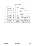


RIX
Industries
MAN
‐
2V3B
‐
4.1V
‐
P1
Page
viii
COMPRESSOR
SPECIFICATIONS
This document is valid for the following RIX compressor models:
2V3B
‐
4.1V
‐
P1A
2V3B
‐
4.1V
‐
P1B
2V3B
‐
4.1V
‐
P1C
2V3B
‐
4.1V
‐
P1E
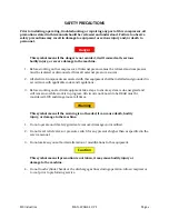
Warning
This equipment is designed only for the specific application noted on this page. It is
the user’s responsibility to ensure the compressor meets the below stated operating
conditions. Deviation from these standards may result in damage to the compressor
and/or operator injury or death.
Gas
Input
Design Gas:
Clean Dry Oxygen
Pressure:
30 to 40 PSIG
Dew Point:
– 40 °F Maximum
Gas
Output
Flow:
10.6 SCFM* at 40 PSIG, 100 °F inlet
Pressure:
2500 PSIG Maximum
*Design basis of SCFM is 70°F and 14.7 psia
General
Design
Design Speed:
540 RPM
Compressor Design:
Three stage, oil-free compression, air-cooled
Cylinder Sizes:
2 1/4” & 1 3/8” & 5/8”
Stroke
Length:
3”
Electrical
Requirements
Drive Motor:
10 HP
Control Circuit Voltage:
230 VAC
P1A
Supply
Power:
208-230VAC/3PH/60HZ
P1B
Supply
Power:
460VAC/3PH/60HZ
P1C
Supply
Power:
380-415VAC/3PH/50HZ
P1E
Supply
Power:
380-415VAC/3PH/60HZ
Operating
Environment
Installation:
Indoors or Weather Protected
Ambient Temperature:
35 to 104 °F
Altitude:
Sea Level to 4500’
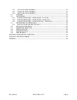
Summary of Contents for 2V3B-4.1V-P1A
Page 46: ...RIX Industries MAN 2V3B 4 1V P1 Page 37 FIGURE 1 GENERAL COMPRESSOR DETAIL 1 4 ...
Page 47: ...RIX Industries MAN 2V3B 4 1V P1 Page 38 FIGURE 2 GENERAL COMPRESSOR DETAIL 2 4 ...
Page 48: ...RIX Industries MAN 2V3B 4 1V P1 Page 39 FIGURE 3 GENERAL COMPRESSOR DETAIL 3 4 ...
Page 49: ...RIX Industries MAN 2V3B 4 1V P1 Page 40 FIGURE 4 COMPRESSION VALVE DETAIL ...
Page 50: ...RIX Industries MAN 2V3B 4 1V P1 Page 41 FIGURE 5 GENERAL COMPRESSOR DETAIL 4 4 ...
Page 51: ...RIX Industries MAN 2V3B 4 1V P1 Page 42 FIGURE 6 FIRST STAGE COMPRESSION STAGE DETAIL ...
Page 53: ...RIX Industries MAN 2V3B 4 1V P1 Page 44 FIGURE 8 SUCTION AND FIRST STAGE PLUMBING DETAIL ...
Page 54: ...RIX Industries MAN 2V3B 4 1V P1 Page 45 FIGURE 9 SECOND AND THIRD STAGE PLUMBING DETAIL ...
Page 55: ...RIX Industries MAN 2V3B 4 1V P1 Page 46 FIGURE 10 FINAL DISCHARGE PLUMBING DETAIL ...
Page 56: ...RIX Industries MAN 2V3B 4 1V P1 Page 47 FIGURE 11 CRANKCASE ASSEMBLY DETAIL ...
Page 57: ...RIX Industries MAN 2V3B 4 1V P1 Page 48 FIGURE 12 CONNECTING ROD DETAIL ...
Page 58: ...RIX Industries MAN 2V3B 4 1V P1 Page 49 FIGURE 13 CONTROL BOX ASSEMBLY DETAIL 1 3 ...
Page 59: ...RIX Industries MAN 2V3B 4 1V P1 Page 50 FIGURE 14 CONTROL BOX ASSEMBLY DETAIL 2 3 ...
Page 60: ...RIX Industries MAN 2V3B 4 1V P1 Page 51 FIGURE 15 CONTROL BOX ASSEMBLY DETAIL 3 3 ...
Page 61: ...RIX Industries MAN 2V3B 4 1V P1 Page 52 FIGURE 16 WIRING SCHEMATIC ...
Page 62: ...RIX Industries MAN 2V3B 4 1V P1 Page 53 FIGURE 17 ELECTRICAL SCHEMATIC ...
Page 65: ...RIX Industries MAN 2V3B 4 1V P1 Page 55 FIGURE 18 FLOW SCHEMATIC ...
Page 70: ...RIX P N 76 713 X76 713 DWG A8042 CUI SP CTI PROPIN ...
Page 71: ...RIX P N 76 713 X76 713 DWG A8042 CUI SP CTI PROPIN ...
Page 77: ......
Page 78: ......
Page 79: ......
Page 80: ......
Page 81: ... ǣ ...
Page 82: ... Ǥ ǣ ...


