


RIX
Industries
MAN
‐
2V3B
‐
4.1V
‐
P1
Page
13
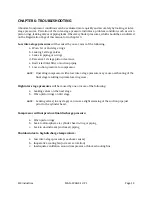
CHAPTER
6:
TROUBLESHOOTING
Abnormal compressor conditions can be evaluated more quickly and accurately by looking at inter-
stage pressures. Variation of the inter-stage pressure indicates a problem condition, such as worn
piston rings, leaking valves or piping leaks. Observe cylinder pressures, which should be as indicated
on the Registration Page of this manual or in chapter 3.
Low
inter
‐
stage
pressures
will be caused by one or more of the following:
a. Worn 1st or 2nd stage rings
b. Leaking 1st stage valves
c. Leaks in piping or o-rings
d. Excessive 1st stage piston clearance
e. Restricted inlet filter or suction piping
f. Low suction pressure to compressor
NOTE
: Operating compressor with a low inter-stage pressure may cause overheating of the
final stage resulting in premature ring wear.
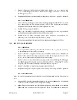
High
inter
‐
stage
pressures
will be caused by one or more of the following:
a. Leaking valves on the next stage
b. Worn piston rings on 3rd stage
NOTE
: Leaking valves (in any stage) can cause a slight warming of the suction pipe just
prior to the cylinder head.
Compressor
will
not
produce
final
discharge
pressure:
a. Worn
piston
rings
b. Leak to atmosphere via cylinder head o-ring or piping
c. Leak in downstream (customer) piping
Shutdown
due
to
high
discharge
temperature:
a. Low inter-stage pressure (see above causes)
b. Inoperative cooling fan (or reverse rotation)
c. Inadequate ventilation around compressor or blocked cooling fins
Summary of Contents for 2V3B-4.1V-P1A
Page 46: ...RIX Industries MAN 2V3B 4 1V P1 Page 37 FIGURE 1 GENERAL COMPRESSOR DETAIL 1 4 ...
Page 47: ...RIX Industries MAN 2V3B 4 1V P1 Page 38 FIGURE 2 GENERAL COMPRESSOR DETAIL 2 4 ...
Page 48: ...RIX Industries MAN 2V3B 4 1V P1 Page 39 FIGURE 3 GENERAL COMPRESSOR DETAIL 3 4 ...
Page 49: ...RIX Industries MAN 2V3B 4 1V P1 Page 40 FIGURE 4 COMPRESSION VALVE DETAIL ...
Page 50: ...RIX Industries MAN 2V3B 4 1V P1 Page 41 FIGURE 5 GENERAL COMPRESSOR DETAIL 4 4 ...
Page 51: ...RIX Industries MAN 2V3B 4 1V P1 Page 42 FIGURE 6 FIRST STAGE COMPRESSION STAGE DETAIL ...
Page 53: ...RIX Industries MAN 2V3B 4 1V P1 Page 44 FIGURE 8 SUCTION AND FIRST STAGE PLUMBING DETAIL ...
Page 54: ...RIX Industries MAN 2V3B 4 1V P1 Page 45 FIGURE 9 SECOND AND THIRD STAGE PLUMBING DETAIL ...
Page 55: ...RIX Industries MAN 2V3B 4 1V P1 Page 46 FIGURE 10 FINAL DISCHARGE PLUMBING DETAIL ...
Page 56: ...RIX Industries MAN 2V3B 4 1V P1 Page 47 FIGURE 11 CRANKCASE ASSEMBLY DETAIL ...
Page 57: ...RIX Industries MAN 2V3B 4 1V P1 Page 48 FIGURE 12 CONNECTING ROD DETAIL ...
Page 58: ...RIX Industries MAN 2V3B 4 1V P1 Page 49 FIGURE 13 CONTROL BOX ASSEMBLY DETAIL 1 3 ...
Page 59: ...RIX Industries MAN 2V3B 4 1V P1 Page 50 FIGURE 14 CONTROL BOX ASSEMBLY DETAIL 2 3 ...
Page 60: ...RIX Industries MAN 2V3B 4 1V P1 Page 51 FIGURE 15 CONTROL BOX ASSEMBLY DETAIL 3 3 ...
Page 61: ...RIX Industries MAN 2V3B 4 1V P1 Page 52 FIGURE 16 WIRING SCHEMATIC ...
Page 62: ...RIX Industries MAN 2V3B 4 1V P1 Page 53 FIGURE 17 ELECTRICAL SCHEMATIC ...
Page 65: ...RIX Industries MAN 2V3B 4 1V P1 Page 55 FIGURE 18 FLOW SCHEMATIC ...
Page 70: ...RIX P N 76 713 X76 713 DWG A8042 CUI SP CTI PROPIN ...
Page 71: ...RIX P N 76 713 X76 713 DWG A8042 CUI SP CTI PROPIN ...
Page 77: ......
Page 78: ......
Page 79: ......
Page 80: ......
Page 81: ... ǣ ...
Page 82: ... Ǥ ǣ ...


