Check for parts online at
www.HuntRiversEdge.com
or call 800-450-EDGE (3343) M-F 8-5
9
Operator's Manual
BOWMAN Ladder Stand
FIGURE
5
FIGURE
6
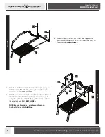
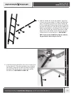
7. Assembly M6 bolt (20) into end of front seat tensioner (6),
screwing M6 bolt (20) all the way into front seat tensioner
(6). SEE FIGURE 5A.
8. Install front seat tensioner assembly (6 and 20) through
left tube and into right tube of Teartuff seat assembly (15),
securing piece as shown using one 1/4-20 X 1-1/2 IN bolt
(23) and locknut (26). Use the provided allen wrench to
tighten M6 bolt (20) through hole in Teartuff seat assembly
(15) to tension seat as desired. SEE FIGURES 5 AND 5A.
FIGURE
5A
15
6
6
20
23
26
FIGURE
6A
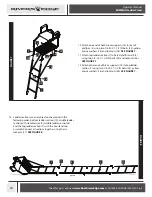
9. Assemble Teartuff seat assembly (6, 15 and 20) to seat side
rails (11) using two 1/4-20 X 2-3/4 IN bolts (27), four yellow
plastic washers (18), two plastic spacers (19) and two
locknuts (26). SEE FIGURES 6 AND 6A.
NOTE: The order of the hardware is imperative for
proper assembly and function please reference
FIGURE 6A, it shows detail of the left side of the seat
assembly, and the correct hardware order.
18
26
27
19
15
11
18
Summary of Contents for RE663
Page 6: ......

