TF2002501-RG English
Page 12 of 14
20190611 V.2
Part List
Part #
Description
Qty
1
Metal Stand
1 pc
2
Burner, Regulator Hose Assembly
1 pc
3
Burner Cover
1 pc
4
Light Arm
1 pc
5
Regulator Hook
1 pc
6
Thermometer
1 pc
Hardware List
Item No.
Item name
Diagram
Qty
A
M6 x 12 BOLT
3
B
M6 FLANGE NUT
2
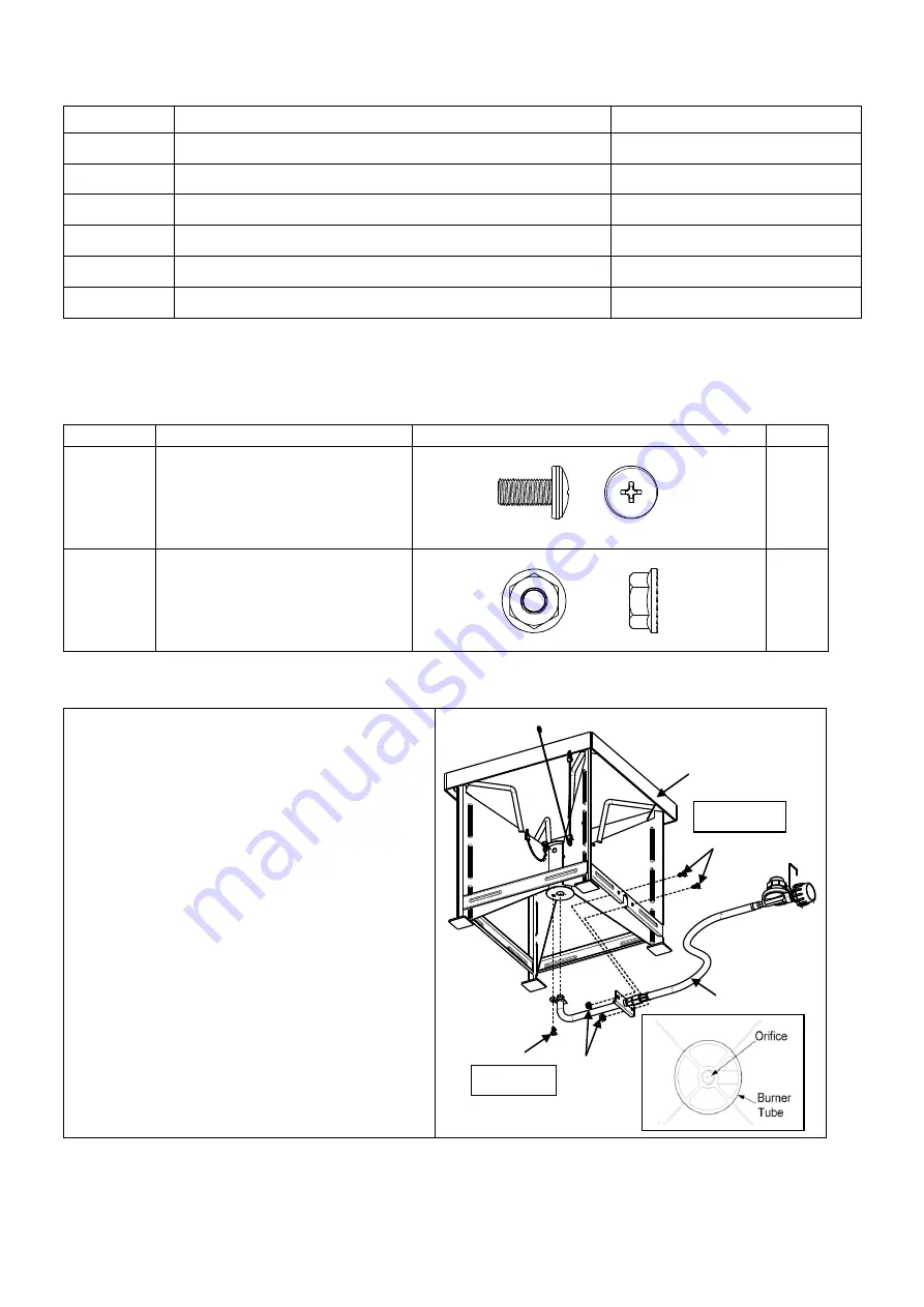
Assembly Instructions:
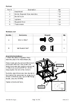
1. Attach the Burner, Regulator Hose
Assembly (#2) to the Metal Stand (#1).
Firstly, make sure the burner orifice should
be located at Burner Tube Center and
fasten the burner tube outlet by using a M6
x 12 Bolt (A). (see the STEP A)
– Don’t
totally tighten the bolt at this moment.
Secondly, attach the burner tube bracket to
the brace of the metal stand by using 2 pcs
of M6 x 12 Bolt (A) and 2 pcs of M6 Flange
Nut (B). (See the STEP B)
Tighten all bolts and Nuts.
2
A
B
A
1
STEP A
STEP B

