background image


  51  of 51 


20190813-Ver.1.0


LIMITED WARRANTY 


1. 

Manufacturer  warrants  this  Product  to  be  free  from  defects  in  workmanship  and  materials  for  a 
period of Ninety (90) days from the date of purchase, PROVIDED claims are submitted, in writing, 
with proof of purchase.     

2. 

If any part of this item fails because of a manufacturing defect within the Limited Warranty Period, 
Manufacturer  offers  to  replace  such  part(s)  provided  that  such  parts  have  not  been  improperly 
repaired, altered, or tampered with or subject to misuse, abuse or exposed to corrosive conditions. 
This  Limited  Warranty  is,  however,  subject  to  certain  limitations,  exclusions,  time  limits  and 
exceptions (Hereinafter “Conditions”) as listed below. Read these Conditions carefully. 

3. 

This Limited Warranty shall be limited to the replacement or repair of any part(s) which Manufacturer 
determines, after reasonable examination, to have been defective at the time of manufacturing and 
manufacturer’s obligation(s) shall be limited to replacement, if any, of defective part(s) which shall 
be shipped at Original Purchaser’s expense to Original Purchaser’s designated shipping address. 

4. 

This  Limited  Warranty  is  given  to  and  covers  the 

ORIGINAL  PURCHASER  ONLY 

and  such 

coverage terminates Ninety (90) days from the date of purchase.


5. 

DAMAGE LIMITATION WARNING:   

IN NO EVENT SHALL MANUFACTURER BE LIABLE FOR 

ANY  INCIDENTIAL  OR  CONSEQUENTIAL  DAMAGES,  INCLUDING  (BUT  NOT  LIMITED  TO) 
LOSS  OF  USE  OF  THE  PRODUCT,  LOSS  OF  TIME,  LOSS  OF  FOOD,  INCONVENIENCE, 
EXPENSES FOR TRAVEL, TRANSPORTATION LODGING EXPENSES, LOSS BY DAMAGE TO 
PERSONAL PROPERTY OR LOSS OF INCOME, PROFITS OR REVENUE. 

6. 

MANUFACTURER’S  OBLIGATION:

    Manufacturer’s  liability  shall  be  limited  to  the  delivery  of  a 

good, merchantable Product and, if necessary, the repair or replacement, at manufacturer’s option, 
of any defective part or unit. 

7. 

TRANSFER  LIMITATIONS:

    This  Limited  Warranty  is  not  assignable  or  transferable.    It  covers 

only the original purchaser. 

8. 

RESERVED  RIGHT  TO  CHANGE:

    Manufacturer  reserves  the  right  to  make  changes  or 

improvements  to  products  it  produces  in  the  future  without  imposing  on  itself  any  obligations  to 
install the same improvements in the products it has previously manufactured. 

9. 

This Limited Warranty gives the Original Purchaser specific legal rights but there may be other rights 
which vary by jurisdiction. 

10.  This warranty does not cover the following items: 

  Chips or scratches on porcelain or painted surfaces. 

  Rust or corrosion is not deemed a manufacturing or materials defect. 

  Discoloration or loss of paint due to handling during assembly, heat or cleaning products. Paint 

may require touch up. 

  Stainless steel discoloration or corrosion. 

  Consumables such as batteries. 


IF CUSTOMER SERVICE BECOME NECESSARY:


1. 

The Original Purchaser is responsible for shipping and handling charges of the returned item(s) 
and replacement parts, if any. 

2. 

All parts to be replaced will need to be shipped before replacement items will be sent. 

3. 

Follow the Customer Service Representative’s instructions exactly. If a return is necessary, it must 
be packed carefully and shipped prepaid. 


Should you encounter any problem, 

CALL US FIRST. 

Do not return product to the store. 

WE CAN HELP. 


                For assistance, contact customer service at 

[email protected]


        or at 

1-888-837-1380

, Mon to Fri, 8:00am – 5:00pm Pacific Standard time 


Manufacturer information 

Rankam (China) Manufacturing Company Limited 

Address: 18/F,. New Lee Wah Centre, 88 Tokwawan Road, Kowloon, Hong Kong.


Summary of Contents for GR2297801-RG-00

Page 1: ...ctions before assembling using the appliance Follow all warnings and instructions when using the appliance Failure to follow these instructions and warnings could result in damage to the product or injury to the user Keep this manual for further reference Should you encounter any problem CALL US FIRST Do not return product to the store WE CAN HELP For assistance contact customer service at custome...

Page 2: ...way from the appliance and immediately call your gas supplier or fire department 5 Hazardous voltage is present which can shock burn or cause death Disconnect the power cord before servicing the grill unless otherwise noted in the owner s manual Failure to follow these instructions could result in fire or explosion which could cause property damage personal injury or death DANGER A MAJOR CAUSE OF ...

Page 3: ...not followed exactly a fire causing death or serious injury may occur WARNING FUELS USED IN LIQUEFIED PROPANE GAS APPLIANCES AND THE PRODUCTS OF COMBUSTION OF SUCH FUELS CAN EXPOSE YOU TO CHEMICALS INCLUDING BENZENE WHICH IS KNOWN TO THE STATE OF CALIFORNIA TO CAUSE CANCER AND CAUSE BIRTH DEFECTS OR OTHER REPRODUCTIVE HARM For more information go to www P65Warnings ca gov WARNING CARBON MONOXIDE H...

Page 4: ...luence of drugs or alcohol Keep the fuel supply hose away from heated surfaces DO NOT put the grill in storage or move it after use Allow the grill to be cool to the touch before moving storing Failure to do so could result in a fire causing property damage personal injury or death The appliance is for household use only DO NOT use this grill for other than its intended purpose Never use natural g...

Page 5: ... cord is disconnected before performing any service or maintenance Always keep the Pellet Hopper dry the wood pellets will expand greatly break apart and even jam the feed system if the pellets get wet or exposed to high humidity Never use heating fuel pellets in the grill due to potential hazardous contaminants and additives that may be present Do NOT expose the appliance to rain or water at any ...

Page 6: ...ng gas appliance then plug appliance into the outlet Use only a Ground Fault Interrupter GFI protected circuit with this outdoor cooking gas appliance Never remove the grounding plug or use with an adapter of 2 prongs Use only extension cords with a 3 prong grounding plug rated for the power of the equipment and approved for outdoor use with a W A marking USE AND INSTALLATION OF LP GAS CYLINDER PR...

Page 7: ...stored outdoors out of the reach of children and MUST NOT be stored in a building garage shed breezeway or any other enclosed space Storage of an outdoor cooking gas appliance indoors is permissible ONLY if the cylinder is disconnected and removed from the outdoor cooking gas appliance The cylinder should ALWAYS be put in an upright position DANGER DO NOT connect this grill to an existing 510 POL ...

Page 8: ...sion causing severe burns bodily harm or death could occur Always use a safety cap when the grill is not connected to a cylinder If you exchange a cylinder with a qualified exchange program be sure the cylinder has a Type 1 valve and an over fill prevention device OPD INSTALLING GAS CYLINDER 1 Check that the cylinder valve is closed by turning the knob in clockwise 2 Place the cylinder into cylind...

Page 9: ...nterclockwise Use a soapy water solution to check all connections for leaks a Leak Test before attempting to light the grill see P 35 If a leak is found turn the tank valve off and do not use the grill until your LP gas dealer can make repairs TO DISCONNECT LP CYLINDER 1 Turn the burner valves off 2 Turn the tank valve off fully turn clockwise to stop 3 Detach the regulator assembly from the tank ...

Page 10: ...10 of 51 20190813 Ver 1 0 PRODUCT DIAGRAM ...

Page 11: ...let 3 Warming Rack Pre assembled 2pcs 2pcs 2pcs 4 Flame Tamer Gas 5 Grease Cup Gas 6 Grease Drip Tray 3pcs 1pc 1pc 7 Flame Tamer Pellet 8 V shaped Grease Drain 9 Grill Body Assembly 1pc 1pc 1pc 10 Grease Bucket Pellet 11 Side Burner Cooking Grate 12 Side Burner Assembly 1pc 1pc 1pc ...

Page 12: ...r 15 Side Burner Grease Tray 2pcs 1pc 1pc 16 Side Lid Handle 17 Side Burner Control Panel 18 Control Knob Bezel 2pcs 1pc 1pc 19 Control Knob 20 Cart Left Panel 21 Cart Left Rear Frame 1pc 1pc 1pc 22 Cart Right Rear Frame 23 Cart Base 24 Cart Rear Panel 1pc 1pc 1pc ...

Page 13: ...art Right Front Frame 27 Cart Frame Connecting Tube 1pc 1pc 8pcs 28 Cart Side Rack 29 Cart Top Rack 30 Tank Holder 1pc 1pc 1pc 31 Left Door 32 Right Door 33 Locking Caster 1pc 1pc 4pcs 34 Cart Right Panel 35 Plastic Insert 36 Door Handle Bezel 1pc 4pcs 4pcs ...

Page 14: ...2pcs 2pcs HARDWARE LIST Item No Item name Diagram Qty A M6x12mm Bolt 72 B M6 Nut 3 C M6x20mm Bolt 4 D M5x8mm Bolt 4 E M4x8mm Bolt 14 F Plastic Rivet 3 G M4x23 Step Bolt 1 Note For Bolt E 12 pcs are stored in the hardware pack and 2 pcs have been pre attached on the related components ...

Page 15: ...15 of 51 20190813 Ver 1 0 Replacement Part List I ...

Page 16: ... Grill Body Auger Drive Motor 9 19 Grill Body Draft Inducer Fan 9 20 Grill Body Feeder Assembly 9 21 Grill Body Pellet Firepot 9 22 Grill Body Auger 9 23 Grill Body Auger Seal Ring 9 24 Grill Body Temperature Detector RTD Sensor 9 25 Grill Body Hopper Lid 9 26 Grill Body Hopper Guard 9 27 Grill Body Hopper Body 9 28 Grill Body Hopper Bottom Panel 9 29 Grill Body Pellet Control Panel Bracket 9 30 G...

Page 17: ... Locking Caster 34 Cart Right Panel 35 Plastic Insert 36 Door Handle Bezel 37 Door Handle 38 Door Magnet Bracket 39 Meat Probe Symbol The following symbols will be shown in each procedure for indication of tightening the bolt and nut if necessary WARNING Please wear gloves while assembling the grill Hand Tighten only at this time Tighten with tools at this time ...

Page 18: ... PROCEDURES Step 1 Connect the Cart Frames 21 22 25 26 with 8 pcs Cart Frame Connecting Tubes 27 as shown below then secure them with 16pcs M6x12 Bolts A Step 2 Attach the Cart Left Panel 20 to the cart assembly using 4pcs M6x12 Bolts A ...

Page 19: ...19 of 51 20190813 Ver 1 0 Step 3 Attach the Cart Right Panel 34 to the cart assembly using 4pcs M6x12 Bolts A Step 4 Attach the Cart Rear Panel 24 to the cart assembly using 10pcs M6x12 bolts A ...

Page 20: ... cart assembly using 12pcs M6x12 bolts A Step 6 Insert the Locking Casters 33 into the threaded holes on the bottom of the cart assembly Tighten the caster by turning in clockwise until it is fully secured Remind to lock all casters by stepping the pedal downwards ...

Page 21: ...21 of 51 20190813 Ver 1 0 Step 7 Fully tighten all the bolts in the cart assembly Step 8 Attach the Tank Holder 30 to the cart assembly using 3pcs Plastic Rivets F ...

Page 22: ...of 51 20190813 Ver 1 0 Step 9 Connect the Cart Side Top Racks 28 29 together using 3pcs M6x12 bolts A and 3pcs M6 Nuts B Step 10 Attach the cart rack assembly to the cart assembly using 5pcs M6x12 bolts A ...

Page 23: ...er 1 0 Step 11 Attach the Door Magnet Brackets 38 to the cart assembly using 4pcs M4x8 bolts E Step 12 Attach the Door Handle 37 Door Handle Bezels 36 and Plastic Inserts 35 to the Left Door 31 using 2pcs M6x20mm bolts C ...

Page 24: ...nd Plastic Inserts 35 to the Right Door 32 using 2pcs M6x20mm bolts C Step 14 Attach the doors to the cart assembly using 8pcs M4x8 bolts E Remark Do not tighten the bolts until all the holes on the hinges are aligned and matched with the cart assembly Then fully tighten all the bolts ...

Page 25: ...are locked Put the Grill Body Assembly 9 carefully on the top of cart assembly Secure the grill body assembly using 4pcs M6x12mm bolts A Be careful to support the grill body and cart assembly during this step Step 16 Attach the Side Burner Brackets 13 to the grill body using 4pcs M6x12mm bolts A ...

Page 26: ...26 of 51 20190813 Ver 1 0 Step 17 Attach the Side Burner Assembly 12 to the grill body and lock it in place as shown Step 18 Secure the side burner assembly by using 2pcs M6x12mm bolts A ...

Page 27: ... 0 Step 19 Remove the pre assemble M4x8 bolts E at side burner gas valve as shown Step 20 Attach the side burner gas valve to the Side Burner Control Panel 17 and the Control Knob Bezel 18 using 2pcs pre assemble M4x8 bolts E ...

Page 28: ...re for side burner to the connector of the side burner igniter Attach the side burner control panel to the control panel bracket Insert the valve outlet orifice into the side burner port Make sure that the valve outlet is inserted STRAIGHTLY into the burner port as shown ...

Page 29: ...ide burner control panel to the grill body using 2pcs M6x12mm bolts A Step 23 Secure the side burner control panel to the side burner assembly using 1pc M6x12mm bolt A Secure the side burner supporting bar to the grill body using 1pc M6x12mm bolt A ...

Page 30: ...er valve Apply light pressure to secure the knob firmly Make sure that the flat end of the pin is aligned with the D shape hole in control knob with the triangle pointing upwards Step 25 Attach the Side Lid Handles 16 to the side lids using 2pcs M5x8mm bolts D for each side lid as shown ...

Page 31: ... 0 Step 26 Attach the V shaped Grease Drain 8 to the grill body using 4pcs M6x12mm bolts A as shown Step 27 Attach the Flame Tamers Gas 4 and Flame Tamer Pellet 7 to the grill body Place them in the holding brackets as shown ...

Page 32: ...32 of 51 20190813 Ver 1 0 Step 28 Place the Grease Drip Tray 6 on the grill as shown ...

Page 33: ...33 of 51 20190813 Ver 1 0 Step 29 Attach the Match Holder 14 to the grill body using 1pc M4x23 step bolt G as shown Step 30 Place the Cooking Grates 1 2 11 on the grill as shown below ...

Page 34: ...Ver 1 0 Step 31 Place the Grease Cup Bucket 5 10 and the Grease Tray 15 on the grill as shown below Step 32 Your unit is fully assembled Make sure to read and follow the Instruction Manual before operating this appliance ...

Page 35: ...st be specified by the manufacturer TO TEST 1 Make sure the control valves are in the OFF position then turn on the gas supply 2 Check all connections from the gas cylinder LP gas regulator and supply valve including all connections to the pipe for the burners Points where the soap water mixture should be applied soap bubbles will appear if a leak is present A Supply tank Cylinder weld B Connectio...

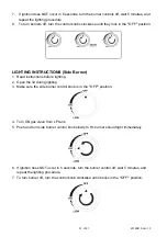
Page 36: ...it should be used Perform the LEAK TEST according to the instructions before operating the grill ALWAYS keep your face and body away from the burner while lighting LIGHTING INSTRUCTIONS Main Burner 1 Read instructions before lighting 2 Open the lid during lighting 3 Make sure all control knobs are in the OFF position 4 Turn ON gas valve from LP tank 5 Light the IGNITION BURNER first Push and turn ...

Page 37: ... Burner 1 Read instructions before lighting 2 Open the lid during lighting 3 Make sure the side burner control knob is in the OFF position 4 Turn ON gas valve from LP tank 5 Push and turn side burner control knob slowly to HI burner should light immediately 6 If ignition does NOT occur in 5 seconds turn the burner control off wait 5 minutes and repeat the lighting procedure 7 To turn burner off tu...

Page 38: ... to the side burner 4 Push and turn side burner control knob slowly to HI burner should light immediately 5 If ignition does NOT occur in 5 seconds turn the burner controls off wait 5 minutes and repeat the lighting procedure DANGER Keep your face and hands as far away from the grill as possible when lighting it FLAME CHARACTERISTICS This procedure outlines how to check for proper burner flame cha...

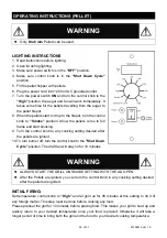
Page 39: ...ome to full flame and start smoking 9 Turn the control knob to any cooking setting desired after the pellets are ignited 10 To turn burner off turn the control knob to the Shut Down Cycle position The draft fan will stay on for 10 minutes WARNING ALWAYS START THE GRILL ON SMOKE SETTING WITH THE LID OPEN After the Pellets are ignited you can turn the control knob to any cooking setting desired afte...

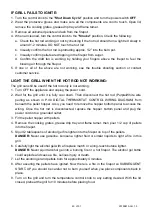
Page 40: ...it is fully cool down Then disconnect the hot rod Purple White wire pairing as shown in P 48 DIGTAL THERMOSTAT CONTROL WIRING DIAGRAM from beneath the pellet hopper Also you need to remove the hopper bottom panel to access the wiring Once the hot rod is disconnected replace the hopper bottom panel and plug the power cord into a grounded outlet 3 Fill the pellet hopper with pellets 4 Remove the coo...

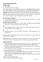
Page 41: ...shooting at P 50 to solve this issue Er2 Temperature detector is short circuit Refer to the section of Trouble shooting at P 50 to solve this issue Whenever either of these alarm conditions occurs you should check to see what caused this condition and fix the problem Please note After shut down cycle running for 10 minutes then you can turn the switch in the OFF position Otherwise it may even caus...

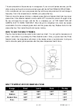
Page 42: ...completely out AT THE SAME TIME BE CAREFUL NOT TO BURN YOURSELF When the grill is completely cool clean any grease accumulation from the v shaped grease drain and the grease drip tray Replace the foil on the grease drip tray Then restart the grill and resume cooking HOW TO USE THE MEAT PROBES Plug the meat probes into the pellet control panel as shown You can get the temperature of probe 1 and pro...

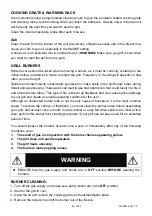
Page 43: ...lean burner venturi tubes for insects and insect nests A clogged tube can lead to a fire beneath the grill STEEL SURFACES There are different stainless steel cleaners available Always use the mildest one for cleaning first and scrubbing in the direction of the grain To touch up noticeable scratches in the stainless steel sand very lightly with dry 100 grit emery paper in the direction of the grain...

Page 44: ...uction that could result in a fire in and around burner tubes This type of fire is known as flashback and can cause serious damage to your grill and create an unsafe operating condition for the user Although an obstructed burner tube is not the only cause of flashback it is the most common cause To reduce the chance of flashback you must clean the burner tubes before assembling your grill and at l...

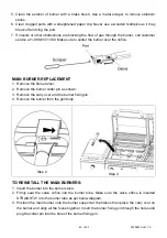
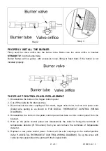
Page 45: ...T 1 Remove the flame tamer 2 Remove the burner cotter pin as shown 3 Remove the carry over and the burner fixing pin 4 Remove the burner from the grill body Step 2 Step 4 TO REINSTALL THE MAIN BURNERS 1 Insert the burner into the burner valve 2 Firmly seat the valve orifice into the burner tube Make sure the valve orifice is inserted STRAIGHTLY into the burner tube as per below diagram 3 Position ...

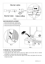
Page 46: ...from the grill body Step 2 Step 3 TO REINSTALL THE SIDE BURNERS 1 Insert the burner into the burner valve 2 Firmly seat the valve orifice into the burner tube Make sure the valve orifice is inserted STRAIGHTLY into the burner tube as per below diagram 3 Position the side burner onto the burner support at the firebox and tighten with the burner fixing bolt as shown ...

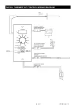
Page 47: ...ire couplings of fan motor auger drive motor hot rod and power cord Detail wire pairing is as shown in P 48 DIGTAL THERMOSTAT CONTROL WIRING DIAGRAM 4 Disassemble the bolts on the pellet control panel then take out the control panel from the bracket 5 Hold up the pellet control panel and disassemble the bolts for fixing the terminals of temperature detector RTD sensor then you can remove the termi...

Page 48: ...48 of 51 20190813 Ver 1 0 DIGTAL THERMOSTAT CONTROL WIRING DIAGRAM ...

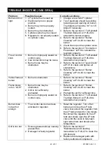
Page 49: ...section of Leak Check at P 35 to check and tighten all connections 3 Refer to the section of Burner Cleaning at P 44 45 to clean the burner Yellow flame at burner 1 Burner is obstructed 1 Refer to the section of Burner Cleaning at P 44 45 to clean the burner Flame blows out on LOW 1 Burner holes may be obstructed 2 Grill is not sufficiently preheated 3 Burner is improperly seated on control valve ...

Page 50: ...s below 150 F for more than 20 minutes Turn the control knob to Shut Down Cycle Wait 2 seconds then set the desired cooking temperature LCD shows Er1 signal Meat probe is not connected correctly or wire disconnected Ensure meat probe is properly connected to controller board Confirm wire connections and check for any damage If problem cannot be resolved please call customer service LCD shows Er2 s...

Page 51: ...ATION Manufacturer s liability shall be limited to the delivery of a good merchantable Product and if necessary the repair or replacement at manufacturer s option of any defective part or unit 7 TRANSFER LIMITATIONS This Limited Warranty is not assignable or transferable It covers only the original purchaser 8 RESERVED RIGHT TO CHANGE Manufacturer reserves the right to make changes or improvements...

Reviews: