Rittal KE 9201 Assembly And Operating Instructions Manual Download Page 8

8

7. Kabel- und Leitungseinführungen 

Es können Kabel- und Leitungseinführungen sowie Verschluss-

stopfen aus kälteschlagbeständigem Kunststoff oder aus Metall 

eingesetzt werden. Alle Kabel- und Leitungseinführungen müs-

sen eine gesonderte EG-Baumusterprüfbescheinigung besitzen 

wie z.B:

PTB 00  ATEX 3119X 

Hersteller Fa. STAHL

PTB 99  ATEX 3121 (Trompete) 

Hersteller Fa. CEAG

DMT 03 ATEX E 051X (Metall) 

Hersteller Fa. HUMMEL

IECEx BVS 07.0020X 

Hersteller Fa. HUMMEL

IECEx BVS 07.0013X 

Hersteller Fa. HUMMEL

IECEx PTB 05.0016X 

Hersteller Fa. STAHL

IECEx PTB 06.0028X (Klimastutzen) 

Hersteller Fa. STAHL

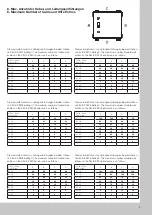
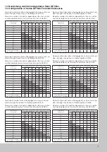
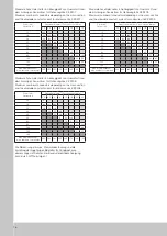
Die max. Anzahl der Einführungen für jede Gehäuseseite ist laut 

Tabelle so gewählt, daß die Seitenwände nicht geschwächt und 

das Gehäuse in seiner Stabilität nicht beeinträchtigt wird.

Alle Kabel- und Leitungseinführungen sind mit einer metallischen 

Gegenmutter zu montieren.

Beim Einsatz von Kabel- und Leitungseinführungen mit Zugent-

lastung und Biegeschutz reduziert sich die Anzahl der möglichen 

Standardverschraubungen.

Eine Mischbestückung von Kabel- und Leitungseinführungen ist 

möglich. Bereiche für eigensichere Stromkreise müssen geson-

dert gekennzeichnet werden.

Nicht benutzte Öffnungen für Kabel- und Leitungseinführungen 

sind mit Blindstopfen, mit gesonderter EG-Baumusterprüfbe-

scheinigung aus Kunststoff oder Metall z.B.:

PTB 99 ATEX 3133 

Hersteller Fa. STAHL

IECEx PTB 05.0013X (Verschlussstopfen) Hersteller Fa. STAHL

zu verschließen.

Die Kabel- und Leitungseinführungen müssen so montiert 

werden, dass eine selbstständige Lockerung verhindert wird 

und eine dauerhafte Abdichtung der Kabel- und Leitungseinfüh-

rungsstellen gewährleistet werden kann.

Die Abstände der Kabeleinführungen sind so zu wählen, dass ein 

Drehmomentschlüssel zum Festziehen  der Kabel und Leitungs-

einführungen sowie der Hutmuttern verwendet werden kann.

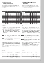
Beim Einbau der Kabel und Leitungseinführungen sind die An- 

zugsdrehmomente zu beachten. Liegen keine kundenspezifischen 

Angaben vor, sind die nachfolgenden Werte anzuwenden.

Eigensichere Stromkreise erfordern separate Kabeleinführungen, 

vorzugsweise in hellblauer Farbe.

Nicht belegte oder frei werdende Kabeleinführungsöffnungen 

sind mit separat bescheinigten Blindstopfen oder mit Ver-

schlussstopfen zu verschließen.

Kabel- und Leitungseinführungen für den Einsatz in Kategorie 

2D benötigen eine separate EG-Baumusterprüfbescheinigung 

für die Kategorie 2D.

7. Cable and wire entries 

Cable and wire entries as well as sealing bungs made of metal 

or cold impact resistant plastic can be used. All cable and wire 

entries must have a separate EU prototype test certificate, for 

example:

PTB 00  ATEX 3119X 


Manufactured by STAHL

PTB 99  ATEX 3121 

 (flared)  Manufactured by CEAG

DMT 03 ATEX E 051X 

 (metal)  Manufactured by HUMMEL

IECEx BVS 07.0020X 


Manufactured by HUMMEL

IECEx BVS 07.0013X 


Manufactured by HUMMEL

IECEx PTB 05.0016X 


Manufactured by STAHL

IECEx PTB 06.0028X    (breathers)  Manufactured by STAHL

The maximum number of entries listed in the table for each side 

of the enclosure has been defined to avoid weakening of the 

side panels or degrading the stability of the enclosure.

All cable and wire entries must be installed using a metal lock 

nut.

The number of possible cable glands decreases if strain relief or 

cable guards are used.

A mixture of cable and wire entries can be used.

Zones for intrinsically safe circuits must be marked.

Unused openings for cable and wire entries must be closed with 

plastic or metal plugs that have a separate EU prototype test 

certificate, for example:

PTB 99  ATEX 3133 


Manufactured by STAHL

IECEx PTB 05.0013X (sealing bungs) Manufactured by STAHL

for sealing.

The cable and wire entries must be installed so that a self-loo-

sening is prevented and the permanent sealing of the cable and 

wire entry locations can be guaranteed.

The distances between the cable entries should be chosen so 

that a torque wrench can be used to tighten the cable and wire 

entries and the box nuts.

The tightening torques must be observed for the installation of 

the cable and wire entries.  If no customer-specific details are 

available, the following values should be used.

Intrinsically safe circuits require separate cable entries, preferably 

in light-blue colour.

Unassigned or exposed cable entry openings must be sealed 

with separately approved plugs or sealing bungs.

Cable and wire entries for use in category 2D require a separate 

EU prototype testing certificate for category 2D.

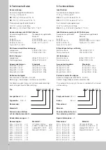
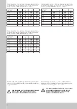
Ex-Kabelverschraubung - metrisch                             Ex cable gland-metric

Größe/

Size

Anzugsdrehmoment Stutzen (Nm) 

Tightening torque Connection piece (Nm)

Anzugsdrehmoment Hutmuttern (Nm) 

Tightening torque Cap nut (Nm)

Anzugsdrehmoment Gegenmutter (Nm) 

Tightening torque Lock nut (Nm)

Kernlochdurchmesser (mm) 

Core hole diameter (mm)

Messing/ 

Brass

Polyamid/ 

Polyamide

Messing/ 

Brass

Polyamid/ 

Polyamide

Messing/Polyamid 

Brass/Polyamide

M 12x1,5

2,5

2,5

2,0

2,0

2,5

12,5

M 16x1,5

4,0

4,0

2,5

2,5

4,0

16,5

M 20x1,5

4,0

4,0

2,5

3,5

4,0

20,5

M 25x1,5

7,5

7,5

12,0

5,0

7,5

25,5

M 32x1,5

7,5

7,5

12,0

12,0

7,5

32,5

M 40x1,5

7,5

7,5

12,0

12,0

7,5

40,5

M 50x1,5

7,5

7,5

12,0

12,0

7,5

50,5

M 63x1,5

7,5

7,5

12,0

12,0

7,5

63,5

Summary of Contents for KE 9201

Page 1: ...ctions Notice de montage et mode d emploi Montage en bedieningshandleidning Montage och bruksanvisning Istruzioni di montaggio e uso Instrucciones de montaje y empleo KEL 9201 KEL 9209 KE 9201 KE 9209 Leergehäuse Klemmengehäuse Empty Enclosure Terminal Enclosure ...

Page 2: ... 19 20 Disposal 19 Zielgruppe Erfahrene Elektrofachkräfte gemäß Betriebssicherheitverordnung und unterwiesene Personen Inhalt Allgemeine Montagehinweise 1 Verwendung 5 2 Zweck der Anleitung 5 3 Sicherheitshinweise 5 4 Normenkonformität 5 5 Technische Daten 6 6 Installation 7 7 Kabel und Leitungseinführungen 8 8 Maximale Anzahl der Kabel und Leitungseinführungen 9 9 Gehäusebefestigung 11 10 Schutzl...

Page 3: ...KS 1448 KS 1449 KS 1453 KS 1454 KS 1466 KS 1467 KS 1453 KS 1454 KS 1468 KS 1469 KS 1479 KS 1480 KS 1400 M 5 x 10 MD 2 5 0 5 Nm SW 4 KE KEL 9208 KE KEL 9209 Einpressmuttern M6 KS 1482 M6 Threaded inserts KS 1482 Montageplattenbefestigung Assembly of mounting plate 1 x A 8 2 x A 8 4 1 x M 8 1 x M 8x25 M D 9 10 Nm M D 2 3 Nm KE KEL 9201 KE KEL 9202 KE KEL 9203 KE KEL 9204 KE KEL 9205 KE KEL 9206 KE K...

Page 4: ...Türanschlages Change of the door hinging KE KEL 9208 und 9209 KE KEL 9208 und 9209 5 MD 0 8 0 2 Nm MD 0 6 0 1 Nm MD 0 8 0 2 Nm MD 0 6 0 1 Nm MD 0 8 0 2 Nm 5 M 5 x 12 M 4 x 8 M 5 x 10 M 5 x 6 M 4 x 8 MD 0 6 0 PZ PZ 2 ...

Page 5: ...binationen und der DIN EN 62208 Leergehäuse Allgemeine Anforderungen soweit anwendbar erfüllt 1 Use The empty enclosures terminal enclosures made of fibre glass reinforced polyester are designed for installation of Ex compon ents and terminals 2 Purpose of these instructions When work is done in areas where there is a risk of explosion the safety of persons and equipment depends on adherence to th...

Page 6: ...200 05 600 x 600 x 200 06 500 x 500 x 300 07 600 x 800 x 210 08 800 x 1000 x 210 09 5 Technical Data Identification Gas explosion endangered areas 0102 II 2G Ex eb IIC CE 0102 II 2G Ex eb IIC T6 T5 CE 0102 II 2G Ex eb ia IIC T6 T5 Dust explosion endangered areas 0102 II 2D Ex tb IIIC IP66 CE 0102 II 2D tb IIIC IP66 T80 C T 95 C Identification according to IEC Ex Scheme Gasexplosionsgefährdete Stau...

Page 7: ...rces or solar radiation may not cause additional heating of the enclosure Elektrische Daten Bemessungsspannung max 1000 V Bemessungsstrom max 125 A Schutzleiterquerschnitt max 35 mm Bemessungsspannung Bemessungsstrom und Bemessungs querschnitt richten sich bei den bestückten Abzweig und Verbindungskästen nach den eingebauten elektrischen Betriebs mitteln Zulässige Umgebungstemperatur 30 C bis 80 C...

Page 8: ...s made of metal or cold impact resistant plastic can be used All cable and wire entries must have a separate EU prototype test certificate for example PTB 00 ATEX 3119X Manufactured by STAHL PTB 99 ATEX 3121 flared Manufactured by CEAG DMT 03 ATEX E 051X metal Manufactured by HUMMEL IECEx BVS 07 0020X Manufactured by HUMMEL IECEx BVS 07 0013X Manufactured by HUMMEL IECEx PTB 05 0016X Manufactured ...

Page 9: ...60 60 M 16 46 46 46 46 M 20 24 24 32 32 M 25 22 22 24 24 M 32 12 12 12 12 M 40 4 4 8 8 M 50 4 4 4 4 M 63 2 2 2 2 Die maximale Anzahl von Leitungseinführungen bei dem Gehäu se KEL KE 9204 beträgt The maximum number of cable wire entries on the KEL KE 9204 enclosure is as follows Größe Seite Size Side A B C D M 12 60 60 96 96 M 16 46 46 66 66 M 20 24 24 40 40 M 25 22 22 36 36 M 32 12 12 24 24 M 40 4...

Page 10: ...6 16 Die Anzahl der Leitungseinführungen bei Sondergehäuseabmes sungen im Rahmen der zulässigen Gehäusegrößen werden von uns gerne ermittelt DIE HINWEISE IN DEN BETRIEBSANLEITUNGEN DER KABEL UND LEITUNGSDURCHFÜH RUNGSHERSTELLER SIND ZU BEACHTEN We would be glad to provide information on the number of cable wire entries for special enclosures that have dimensions within the approved range of enclos...

Page 11: ...PA Leiter mit einem handelsüblichen Kabel schuh passenden Querschnitts und Ringdurchmessers zu ver sehen Die gewählten Kabelschuhe sollten der Norm DIN 46234 für Ringkabelschuhe oder der Norm DIN 46235 für Rohrka belschuhe entsprechen Diese Forderung gilt sowohl für einen massiven Einzelleiter als auch für einen mehrdrahtigen Leiter 10 PE conductor equipotential bonding conductor PA connection The...

Page 12: ...hsleiteranschlüsse die nicht in M 8 ausgeführt gelten folgende Drehmomente Schraubengröße Drehmoment Nm M 4 2 0 M 5 3 2 M 6 5 0 M 8 10 0 M10 16 0 The terminals for the protective earth and equipotential bonding conductor are designed to accommodate at least one conduc tor The cross sections must be selected as follows Cross section of the phase wire of installation S Minimum cross section of the a...

Page 13: ...nd nichteigensicheren Stromkreisen und Klemmen siehe folgende Abbildungen 11 Configuration and internal components non intrinsically safe circuits Use Ex terminal blocks that comply with EN 60079 7 Section 13 to configure the terminal blocks These Ex components are part of an Ex equipment and as such they may only be used together with a partially certified enclo sure All approved terminal blocks ...

Page 14: ...werden Bei farblicher Kennzeichnung ist ausschließlich die Farbe hellblau einzusetzen Dies gilt insbesondere für Anschluss mittel Kabel und Leitungen sowie für Leitungsführungen 13 Configuration and internal components intrinsically safe circuits Terminals for intrinsically safe circuits must be separated from non intrinsically safe circuits You can achieve separation through spacing terminal spac...

Page 15: ...83 50 5 27 69 63 9 32 113 80 12 35 127 100 15 33 125 13 160 max Klemmenanzahl max numbers of terminals 60 60 60 46 37 30 24 24 Maximale Anzahl der Leiter in Abhängigkeit von Querschnitt und dem zulässigen Dauerstrom für Gehäusegröße KE 9204 Maximum number of conductors depending on the cross section and the allowable constant current for enclosure size KE 9204 Strom in A Current in A Querschnitt i...

Page 16: ...ent in A Querschnitt in mm2 Cross section in mm2 1 5 2 5 4 6 10 16 25 35 10 181 16 62 121 468 20 26 70 136 25 33 77 148 35 22 58 144 50 8 47 119 63 16 5 197 80 21 61 220 100 26 58 125 2 23 160 max Klemmenanzahl max numbers of terminals 343 343 343 259 208 174 139 139 Die Berechnung der max Klemmenbestückung und die Erstellung der zugehörigen Beiblätter für Sondergehäuse abmessungen im Rahmen der B...

Page 17: ...50 20 von 81 25 25 63 53 von 133 40 Summe 98 100 15 Installation and configuration information According to DIN EN 60079 and DIN EN 0 the maximum number of conductors depending on the cross section and the allowable constant current is used to determine confor mance to the temperature parameters Conductor and terminal configuration Current in A Cross section in mm2 1 5 2 5 4 6 10 16 25 35 10 218 X...

Page 18: ... die Leitungen nicht unter den Trag schienen hindurch geführt werden können ist mindestens 2xb einzuhalten Bestückungsbeispiele 16 Minimum cable routing spacing To ensure that cable routing is orderly and the conductors are securely fastened to the terminal blocks sufficient spacing must be maintained between the wall of the enclosure and the terminals blocks or terminal block sockets The minimal ...

Page 19: ...20 Entsorgung Es sind die nationalen Abfallbeseitigungsvorschriften zu beachten FÜR SPEZIELLE FRAGEN STEHEN WIR IHNEN GERNE ZUR VERFÜGUNG WENDEN SIE SICH BITTE AN DIE FÜR IHR GEBIET ZUSTÄNDIGE RITTAL VERTRETUNG 17 Commencing operation Before you apply power for the first time you must check the following items the enclosure must be properly installed the enclosure must not be damaged this applies ...

Page 20: ...20 ...

Page 21: ...21 ...

Page 22: ...22 ...

Page 23: ...23 ...

Page 24: ...2 D 35726 Herborn Phone 49 0 2772 505 0 Fax 49 0 2772 505 2319 E Mail info rittal de www rittal de Enclosures Power distribution Climate control IT infrastructure Software services 10 2011 A3881902TP73 03 14 A 30850 03 KE 74 309 805 ...

Reviews: