background image

HCM705B

-

High Accuracy Gyro Compass

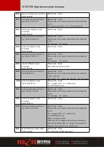
After took the eighth point, H and R are the same , then

calibrate –P angle .

Refer to the left Pic.C: starting point H=0°

R=0°,

P=-15°,please keep this posture for 2-3 seconds don’t

move, the system will take the ninth point.

After took the ninth point, again rotate 90 °horizontally,

please keep this posture for 2 to 3 seconds don’t move,

the system will take the tenth point.

After took the tenth point, again rotate 90 °horizontally,

please keep this posture for 2 to 3 seconds don’t move,

the system will take the eleventh point.

After took the eleventh point, again rotate 90 °horizontally, please keep this posture for 2 to 3

seconds don’t move, the system will take the twelfth point.

After took the twelfth point, H and R are the same , then

increase –P angle value .

Refer to the left Pic.D: starting point H=0°

R=0°,

P=-55°,please keep this posture for 2-3 seconds don’t

move, the system will take the thirteenth point.

After took the thirteenth point, again rotate

90 °horizontally, please keep this posture for 2 to 3

seconds don’t move, the system will take fourteenth

point.

After took the fourteenth point, again rotate

90 °horizontally, please keep this posture for 2 to 3 seconds don’t move, the system will take

the fifteenth point.

After took the fifteenth point, again rotate 90 °horizontally, please keep this posture for 2 to 3

seconds don’t move, the system will take the sixteenth point.

After took the sixteenth point then finished P

calibration, then calibrate R,R(Roll value)can calibrate

alternately .

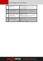
Refer to the left Pic.E: starting point H=0°

R=+15°,

P=0°,please keep this posture for 2-3 seconds don’t

move, the system will take the seventeenth point.

After took the seventeenth point, again rotate

90°horizontally, alternate the negative Roll value

R=-15

°

,

please keep this posture for 2 to 3 seconds

don’t move, the system will take the eighteenth point.

After took the eighteenth point, again rotate

90°horizontally, alternate the positive Roll value

R=+15

°

,

please keep this posture for 2 to 3

Summary of Contents for HCM705B

Page 1: ...01 Tilt sensor production standards GB T 191 SJ 20873 2003 inclinometer general specification of Level Gyro accelerometer test standard QJ 2318 92 Gyro accelerometer test methods Software development...

Page 2: ...M705B with small volume low power consumption can be applied in antenna stable vehicles systems integration and many other fields high shock resistance and high reliability make compass work normally...

Page 3: ...5 Measuring range 0 1 30 Measuring range 0 1 60 Measuring range 0 2 180 Measuring range Roll tilt range 180 Resolution 0 1 Calibration Hard iron calibration Yes Soft iron calibration Yes Magnetic fiel...

Page 4: ...iron magnets engines and other magnetic objects as much possible as you can Need control over 30CM distance different magnetic interfere the compass in different distance at least even there are these...

Page 5: ...ic material then proceed with heading accuracy measurement of course the rotating rod perpendicular to the rotating platform as much as possible to avoid large external magnetic field interference Doi...

Page 6: ...HCM705B High Accuracy Gyro Compass Dimension Size L W H 94 31 24MM...

Page 7: ...use about 2 seconds the internal CPU automatically calculate just sampling data after the calculation will return a set of data is the percentage value of the data just gain 5 Then send the save calib...

Page 8: ...ic level about 90 to change do not require too precise Example as left Pic A starting point for H 0 R 0 P 15 firstly calibrate the pitch value P please keep this posture for 2 to 3 seconds don t move...

Page 9: ...will take the thirteenth point After took the thirteenth point again rotate 90 horizontally please keep this posture for 2 to 3 seconds don t move the system will take fourteenth point After took the...

Page 10: ...point After took the twenty third point again rotate 90 horizontally alternate the negative Roll value R 55 please keep this posture for 2 to 3 seconds don t move the system will take the twenty fourt...

Page 11: ...e calibration Click this button keep the compass shaking state to avoid incorrect calibration of the acquisition Save stop calibration and save data Specific calibration method please refer to this sp...

Page 12: ...etting failure 0X07 Read declination command 68 04 00 07 0b Data domain 0byte No Data domain command 0X87 Sensor answer reply E g 68 06 00 87 02 08 97 Data domine 2byte Data domain in the number means...

Page 13: ...uccess FF Failure 0X0C Setting angle output mode 68 05 00 0C 00 11 Data domain 1byte 00 answer reply mode 01 Auto output mode Default answer reply mode 0X8C Sensor answer reply command E g 68 05 00 8C...

Page 14: ...node must send one time 0X88 Sensor answer reply command 68 05 00 88 xx cs Data domain 1byte Data domain in the number means the sensor response result xx 0 18 00 0 point 01 1 point 02 2 points 0F 15...

Page 15: ...and be used 68 04 00 14 18 Data domain 0byte 0X94 Sensor answer reply command E g 68 YY 00 94 XX ID1 DA1 DA2 DA3 DA4 ID2 DB1 DB2 DB3 DB4 CE Data domain 5 46byte Data domain in the number means the sen...

Page 16: ...Data domain 1byte Data domain in the number means the sensor response result 00 Success FF Failure 0X50 Set the geomagnetic threshold judgment command 68 06 00 50 24 16 CS Data domain 2byte MAX BYTE4...

Page 17: ...ess Default is 00 Command word Fixed 84 Pitch angle The first byte is the sign bit 00 is positive angle 10 is negative angle The second byte is the integer bit Is compressed BCD code The third byte is...

Page 18: ...HCM705B High Accuracy Gyro Compass...

Reviews: