background image

HCM370B&375B-MP

HIGH ACCURACY 3D DIGITAL COMPASS

○Inclinometer ○3D compass ○Digital inclinometer ○Accelerometer ○Gyro ○North finder ○INS&IMU

SINCE2008

·

Inertial Attitude Measurement Manufacturer

sensor response
00 start succeeded

FF start failed

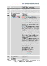
Note: compass will return data every point is take until calibration stop, format as below:

0X88

Compass reply calibration take
point number
Eg.:

68 05 00 88 07 94

Data field

1byte

The number in the data field that represents the
calibration point picked up by the sensor (hexadecimal)

0X09

Stop calibration command

68 04 00 09 0D

data field

0byte

no data command

0X89

sensor repsond
Eg.:

68 10 00 89

00 00 78

00

01 13

00 00 40

00 64 74

5B

Data field

12byte

SA AA BB

SC CD DD

SE EF FF

SG GG HH

SA AA BB

: 3 characters represent the calibration residual

coefficient of the sampling point. < 1 is normal. The
smaller the value is, the more reliable the calibration is.

SC CD DD

: The three characters represent the uniformity

of the distribution of sampling points in all directions of
the 3D calibration. The score should be less than 6%.
The smaller the value, the more uniform the distribution
of sampling points is.

SE EF FF

: 3 characters represent the distribution range

of the tilt Angle of the 3D calibration sampling point, and
the score should be between 0 and 1. The smaller this
value is, the more extensive the spatial coverage of the
sampling point is.

SG GG HH

: 3 characters represent the amplitude of the

single side of the maximum Angle of pitch Angle and roll
Angle of the compass calibration sampling point, and the
score should be > 45°. The larger this value is, the more
sufficient the spatial distribution of the calibration
sampling point will be.
Note: the above score values are for reference only. If the
above score requirements are met, it means that the
sampling conditions of this calibration are excellent and
the accurate azimuth accuracy is not necessarily
obtained.
The first byte high 4 bits is sign bit, 1 negative, 0 positive

The first byte low 4 bits is hundreds.
The second byte high 4 bites are tens.
The second byte low 4 bites are ones.
The third byte high 4 bits are tenths.
The third byte low 4 bits are percentile.
In the left example, the Angle is

SA AA BB

0.78

SC CD DD

1.31%

SE EF FF

0.4

SG GG HH

64.74°

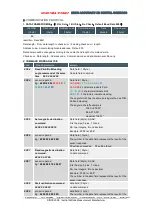
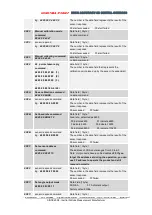
0X44

Auto calibration mode
command
68 04 00 44 48

Data field

0byte

no data command

0XC4

sensor repsond

Data field

1byte

Summary of Contents for HCM370B

Page 1: ...ASS Inclinometer 3D compass Digital inclinometer Accelerometer Gyro North finder INS IMU SINCE2008 Inertial Attitude Measurement Manufacturer V1 1 RION HCM370B HCM375B MP HIGH ACCURACY 3D DIGITAL COMPASS Technical Manual Patent No ZL201730609573 9 ...

Page 2: ...ION CERTIFICATION Enterprise quality system standard ISO9001 2015 standard Certification No 128101 High tech Enterprise Certificate No GR201844204379 China National Intellectual Property Appearance Patent Patent No ZL 201730609573 9 Revision time 2021 6 3 Product functions parameters appearance etc will be adjusted as technology upgrades Please contact our pre sales business to confirm when purcha...

Page 3: ...r are available This product integrates a three axis magnetic field sensor and a three axis acceleration sensor It uses an industrial single chip computer with high reliability and strong anti interference ability to calculate heading data in real time and uses a three axis accelerometer to compensate for a wide range of tilt angles With high performance high stability products small size and low ...

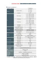
Page 4: ...tic Calibration Available Soft Magnetic Calibration Available Magnetic Filed Interference Calibration Method Rotate 360 Horizontally Vertical Rotation Optional RS 232 RS485 TTL 5Pin Quick Plug Connector Interface Start Delay 50ms Max Output Rate 20Hz s Communication Rate 2400 115200baud Output Format Binary High Performance Protocol Power Supply Power Voltage Default DC 5V Current Max 30ma Ideal C...

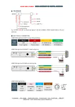
Page 5: ...utput Wiring Definition Cable Color Definition BLACK RED YELLOW GREEN GND Power negative DC 5V Power positive TTL RS232 RXD OR RS485 D TTL RS232 TXD OR RS485 D HCM370B single board RS232 TTL output wiring map HCM370B single board RS485 output wiring map HCM375B Wiring Definition Cable Color Definition BLACK PINK BLUE BROWN GND Power negative RS232 RXD OR RS485 D RS232 TXD OR RS485 D DC 5V Power po...

Page 6: ...agnetic medium around In order to ensure optimal measurement environment please must use the M3 anti interference screws for installation Although it can compensate the moderate deviation in the stable magnetic environment but it can not compensate the changed magnetic interference Please pay much attention to the wire with DC will generates a magnetic field because if the DC change then the magne...

Page 7: ...o the rotating platform as much as possible to avoid large external magnetic field interference Doing so can reduce the compass turning radius to scientifically improve the measurement accuracy This is just to provide the installation of the laboratory must be flexible to deal with the specific situation E g is mounted in the car HCM505B should do its installation in the perpendicular to the movem...

Page 8: ...ommand and the compass will return a response every time it takes a point Please refer to the communication protocol 4 After taking 24 calibration points according to the calibration procedure send the stop calibration command 68 04 00 09 0D click the stop button at this time the electronic compass pauses for about 1 second the internal CPU automatically calculates the sampled data and returns a s...

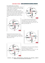
Page 9: ... 2 to 3 seconds and the system will take the first point After taking the first point rotate it 90 horizontally to sample 2nd point so as for 3rd and 4th point After taking the 4th point both H and R remain unchanged and then increase the P angle value Refer to Pic B Starting point H 0 R 0 P 70 the same way to take point 5th 8th After taking the 8th point both H and R remain unchanged and then cal...

Page 10: ...ter taking the 19th point rotate it horizontally by 90 change the negative roll value R 15 keep this attitude for 2 to 3 seconds and the system will take the 20th point After taking the 20th point increase R roll value for calibration Refer to the picture Pic F Starting point H 0 R 70 P 0 Please keep this attitude for 2 to 3 seconds the system will take the 21st point After taking the 21st point r...

Page 11: ...ld 9byte AA AB BB CC CD DD EE EF FF AA AB BB 3 characters indicate Pitch CC CD DD 3 characters indicate Roll EE EF FF 3 characters indicate Heading The angle format has the same parsing method as Pitch Roll and Heading The angle in the left example is Pitch 010 50 Roll 010 05 Heading 104 01 0X06 Set magnetic declination command 68 06 00 06 02 08 16 Data field 2byte SA AB S is the sign 0 plus 1 min...

Page 12: ...he more uniform the distribution of sampling points is SE EF FF 3 characters represent the distribution range of the tilt Angle of the 3D calibration sampling point and the score should be between 0 and 1 The smaller this value is the more extensive the spatial coverage of the sampling point is SG GG HH 3 characters represent the amplitude of the single side of the maximum Angle of pitch Angle and...

Page 13: ... 0byte no data command 0X8A sensor respond command Eg 68 05 00 8A 00 8F Data field 1byte The number in the data field represents the result of the sensor response 00 succeeded FF failed 0X0B Set baud rate command 68 05 00 0B 02 12 Data field 1byte baud rate defaulted as 9600 00 indicate 2400 01 indicate 4800 0 indicate 9600 03 indicate 19200 04 indicate 38400 05 indicate 115200 0X8B sensor respond...

Page 14: ...degrees Vertical downward installation When the compass is placed vertically downward the roll and pitch angle output is zero degrees 0XAA sensor respond command Eg 68 05 00 AA 00 AF Data field 1byte The number in the data field represents the result of the sensor response 00 succeeded FF failed 0X41 Query installation type command 68 04 00 41 45 Data field 0byte 0XC1 sensor respond command Eg 68 ...

Page 15: ...ometer Gyro North finder INS IMU SINCE2008 Inertial Attitude Measurement Manufacturer Add 4th Floor Block 1 COFCO FUAN Robotics Industrial Park Da Yang Road No 90 Fuyong Distict Shenzhen City China Tel 86 755 29657137 86 755 29761269 Fax 86 755 29123494 E mail sales rion tech net Web www rion tech net ...

Reviews:

Related manuals for HCM370B