15
16
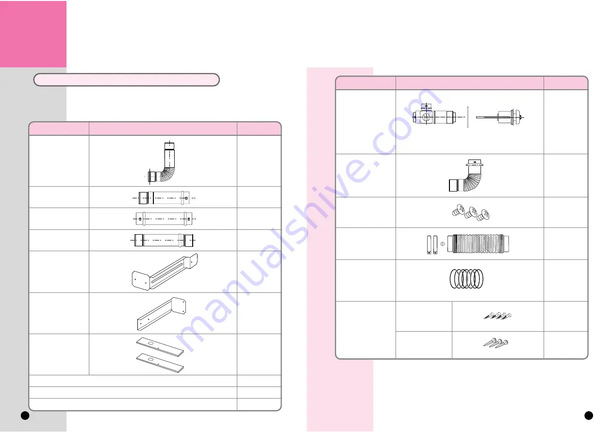
Connection Manifold
Sleeve Plate Terminal Body
Page 1: ...5 MAINTENANCE TROUBLESHOOTNG THE HEATER 11 12 15 27 28 29 30 31 has 17 4 13 6 T...
Page 2: ...The serial number of the heater must be supplied prior to any claim being processed IMPORTANT INFORMATION 1 Gas safety Installation Use regulations 1998 are the Rules in force In your own interest and...
Page 3: ...5 to 6 not no not...
Page 4: ...rom a vertical drain pipe or soil pipe 150mm H From an internal or external corner 200mm I Above ground roof or balcony level 300mm J From a surface facing the terminal 600mm K From a terminal facing...
Page 5: ...flue terminal Flue terminal must be kept clear of bags or empty cans so it does not get blocked gas type and pressure are compatible with the appliance Diagram on the right shows minimum clearances a...
Page 6: ...11 Warm air Swing Louvre Air Flue Terminal 12 in point Alternatively remove plug and wire into a double pole switched 3A fused spur s damage Dirty Open the gas valve fully...
Page 7: ...eater For Safety if you push the stop button during operation the heater will stop To alter the heater you must cancel the lock function When glow the Lock function is set l ure ure always While the t...
Page 8: ...15 16 Connection Manifold Sleeve Plate Terminal Body...
Page 9: ...e 400 must be used e 17 18...
Page 10: ...t flexible hose to heater and tighten band with screw driver Connect air inlet hose to the flue manifold Tighten band with screw driver to secure hose Connect the extendable flue tube to the exhaust p...
Page 11: ...t grease on connecting O rings Use the same air inlet hose length as the length of the flue manifold 21 22 Sleeve plate Terminal Body Concentric Port Connection Manifold Flue Tube of Unit Flue Tube of...
Page 12: ...un If condensed water comes in to the heater the water tray can overflow Do not run flue more than 2m vertically s of flue tube must be same Low Spot 23 24 This is done by pulling the outside terminal...
Page 13: ...to HI turn control to ON Unit should ig nite within 10 seconds If unit does not ignite first time it will spark again after 10 seconds x If unit does not ignite there may be air in the gas line Turn...
Page 14: ...ruction Gas Type Gas Pressure Convection Fan coil resistance PCB voltage to Convection Fan PCB voltage to Overheat Circuit Thermal Fuse Resistance Overheat Switch Resistance CI Room Temp Sensor Faulty...
Page 15: ...MAINTENANCE doe gh attempt a Repeat the from occurs dust this Rinnai UK Do not attempt to disassemble or repair the product unless trained to do so 29 30...
Page 16: ...TROUBLESHOOTING THE HEATER Rinnai UK 17 4 1 2 in BSP o re re ed re plate a re t Refer to the list below 31 32...
Page 17: ...ed and equipped to give you the best service on your Rinnai appliance If you require service please ring the contact numberon this page Notes 33 9 Christleton Court Manor Park Runcorn WA7 1ST 01928 53...
Page 18: ...nstructions before lighting the appliance This appliance shall be installed in accordance with these Manufacturers Installation Instructions Local Gas Fitting Regulations any other relevant Statutory...