background image

 Installation & Servicing Instructions E-Range

5

Observe the following rules of safety:
-

All work on the boiler must take place in a dry environment.

-

Rinnai boilers must never be in operation without their housing, except in connection
with maintenance or adjustments (see Chapter 13 and 14).

-

Never allow electrical or electronic components to come into contact with water.

Carry out the following tasks in connection with maintenance, etc. to an already-

installed boiler:

-

Shut down all programs

-

Close the gas isolation valve

-

Isolate the electrical supply to the appliance.

-

Close the isolation valve of the boiler’s intake connection

Take note of the following when maintenance or adjustments are needed:
-

The boiler must be able to function during these activities; for this reason, the boiler’s
supply voltage, gas pressure and water pressure must be maintained. Ensure that
there is not a source of potential danger during these activities.

Following maintenance or other activities; always check the installation of all
parts through which gas flows (using leak detection spray).

Following maintenance or other activities, always replace the housing and
secure it with the screw behind the door at the front of the casing.

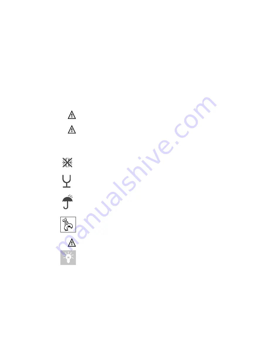
The following (safety) symbols may be encountered in these installation instructions
and on the boiler:

This symbol indicates that the boiler must be stored away from frost.

This symbol indicates that the packaging and/or contents can be damaged as
a result of insufficient care taken during transport.

This symbol indicates that, whilst still in its packaging, the boiler must be
protected from weather conditions during transport and storage.

KEY-symbol. This symbol indicates that assembly or dismantling, must be
carried out.

ATTENTION symbol. This symbol indicates that extra attention must be paid
in connection with a particular operation.

Useful tip or advice

Summary of Contents for E32S

Page 1: ... 10 08 Changes reserved I n s t a l l a t i o n S e r v i c i n g Instructions These instructions to be retained by user Boiler G C No E 32S 41 310 13 CEPIN0063BR3405 High efficiency condensing system boiler E32S ...

Page 2: ...water pressure boiler power of 50 is possible The installation needs to be topped up Operation indication in the first display position of technical read out Water pressure is to high 2 8 bar if HIGH indication remains continuously visible theboileristakenoutofoperation The installation pressure needs to be decreased by draining water Water pressure is to low 0 7 bar FILL indication remains contin...

Page 3: ...trols 21 9 1 Explanation of the function keys 22 10 Filling and venting the boiler and installation 23 11 Commissioning the boiler 24 11 1 Central Heating system 24 11 2 Adjustments 25 11 3 Activating factory settings green key function 27 12 Isolating the boiler 28 13 Commissioning 28 13 1 Checkingforcontamination 29 13 2 Checking the CO2 30 14 Maintenance 31 14 1 Thefrequencyofmaintenance 31 14 ...

Page 4: ... with its intended location e g gas type power source and exhaust classification RelevantInstallation ServiceandUsermanuals Rinnai Flue system guide Rinnai Digital room thermostat 2 Regulations The following regulations apply to installation of Rinnai central heating boilers Legislation and Regulations Gas Safety Installation and Use All gas appliances must by law be installed by a competentperson...

Page 5: ...ained Ensure that there is not a source of potential danger during these activities Following maintenance or other activities always check the installation of all parts through which gas flows using leak detection spray Following maintenance or other activities always replace the housing and secure it with the screw behind the door at the front of the casing The following safety symbols may be enc...

Page 6: ...ect on the heat exchanger and the function of the boiler is drained through an internal siphon The boiler is provided with an intelligent control system CMS Control Management System The boiler anticipates the heat demand of the central heating system When an outside sensor is connected the boiler works weather dependantly This means that the boiler control measures the outside temperature and flo...

Page 7: ...e at least 250 mm working space in order to be able to fit a coaxial flue system On the left side of the boiler at least 50 mm and on the right side 10 mm must be reserved to allow fitting or removing of casing The location of the boiler can be determined by using the template Removethecasingoftheboiler Thecasingisalsotheairboxoftheboilerandissecured with a screw behind the door at the front Also ...

Page 8: ... g mm 215 R pipe lenght of c mm 40 S pipe lenght of c f and r mm 160 T back centre of pipe c mm 26 U back centre of pipe f g and r mm 50 dimensions table 1 dimensions in mm figure 2 wall ceiling minimal 250mm minimal 10 mm D F R S C T Q H J K L G U E A type of unit E32S flue gas system air supply mm 80 125 gas pipe g female central heating flow pipe f mm 22 central heating return pipe r mm 22 cond...

Page 9: ...e supplied service valves directly under the boiler in the flow and return pipe When removing the plastic sealing caps from the pipes contaminated testing water may be released The boiler has a self adjusting and self protecting control system for the load This means thetemperaturedifferencebetweentheflowandreturnwaterischecked Table3showsthe water displacement which supplies the circulation pump ...

Page 10: ... the waste discharge together with the condensation discharge pump index lines graph 1 If all or a large part of the radiators are provided with thermostatic radiator valves it is advisabletouseanautomaticbypassinordertopreventflowproblemsintheinstallation The boiler is designed to be used on a sealed system only Use only potable water for filling the heating system When the water hardness of the ...

Page 11: ... to the terms of the warranty in the event of failure to observe the regulations pertaining to plastic underfloor heating pipes 6 4 Gasconnection Theappliancepipeisfittedwithaninternalthread intowhichthetailpieceoftheisolation valvecanbescrewed United Kingdom ThegassupplymustcomplytothecurrentGasSafety Installation Use Regulations Ireland Irish standard 813 Domestic gas installations The connectio...

Page 12: ...room The drain connection should have a minimum diameter of 32mm Connect the condensation drain pipe according to the actual regulations The following components are connected to the collective condensation drain pipe Condensationdischarge Safety valve Draining of the condensation water to the external rain guttering is not permitted in view of the danger of freezing Before putting the boiler into...

Page 13: ...haust system and air supply system must comply with United Kingdom The flue gas outlet and air supply installation must comply with the current regulation requirements IGE UP 10 and BS 715 Ireland Irish standard is 813 section 9 10 1 Room sealed system Examples of room sealed systems figure 4 PP MW PP MW PP MW Boiler Class C Permitted only when the air intake and the flue gas outlet are in the sam...

Page 14: ...n the vicinity see fig 5 In certain weather conditions condensation may also accumulate on the outside of the airinletpipe Suchconditionsmustbeconsideredandwherenecessaryinsulationofthe inlet pipe may be required In cold and or humid weather water vapour may condense on leaving the flue terminal The effect of such plumeing must be considered The terminal must not be located in a place where it is ...

Page 15: ...n towards the outside to prevent rainwater from coming in The appliance produces a white wisp of condensation plumeing This wisp of condensation is harmless but can be unattractive particularly in the case of outlets in outside walls The flue gas duct for 80 125 are push fit connections see figure 6 Cutting the pipe goes as follows Take out the inner tube by turning it until it releases from its s...

Page 16: ...distancebetweenboilerandroof terminal B When using bends the noted value behind every bend should be deducted from the maximum straight length ø80 125mm B in m E32S Maximum straight lenth 80 125 24 87 bend resistance length 2 8 45 bend resistance length 1 1 Concentric flue system Dimensions flue gas system and air supply system Table 6 Example A 32kW with a concentric flue gas system ø80 125mm has...

Page 17: ...xternal hot water supply The separate Rinnai Infinity water heater has to be mounted according the instructions supplied with the mounting bracket together with the E boiler Each appliance must be served via its own gas isolation valve and flue system ...

Page 18: ...heir allocated connections All other types or makes of room thermostats or controls which are used must have a Volt free contact When using an on off thermostat or control it is possible that an anticipating resistance must be installed in order to prevent too high temperature fluctuations As a standard rule this means mercury thermostats This resistance wire can be ordered by your supplier and mu...

Page 19: ...Installation Servicing Instructions E Range 19 electrical diagram figure 8 ...

Page 20: ...r case and may be interchanged Connect the outside sensor to terminal 18 and 19 on the terminal block in the boiler see figure 7 and 8 Mountinginstructions 1 Route the sensor cable to the mounting location 2 Loosen lid screws from sensor case and remove top 3 Mount sensor base with enclosed central fastening screw Use sealing ring The cable outlet must be directed downwards 4 Insert the sensor cab...

Page 21: ... the right the flow temperature the water pressure in the installation When a message error or blocking code is necessary this will be shown instead of the technical read out To switch over from the Good state to the Technical read out and vice versa Press the STEP key for 5 sec Whenthesystemhasbeenfilledtheautomaticventingprogramstarts whenaprogramhas been selected by pressing the key for Central...

Page 22: ...etrieved After pressing for 5 seconds it switches from the Good state to technical read out and vice versa Reset key After briefly pressing for unlocking errors ending the access code After pressing for 5 seconds an operating stop is made for example for activating the automatic venting program Some keys have other functions These functions are only active when according to the procedure described...

Page 23: ...tivate the functions in use heating DHW and or pump 13 If A xx appears on the display wait for 17 minutes 14 Check the water pressure and if necessary top it up to 1 5 to 1 7 bar 15 Close the filling loop 16 Press the STEP button 17 Be sure that the filling loop is closed 18 After the automatic de aeration program A xx is finished the boiler will return to the Good state or Technical read out Chec...

Page 24: ...in the current Gas Safety Installation Use Regulations The boiler does not require adjustment of the burner pressure and air quantity because it is self adjusting and is factory set at the correct value 11 1 Central Heating system Provided there is a heat requirement from the thermostat or control the central heating program will be put into operation by means of the key central heating program Th...

Page 25: ...ers INFO Information chapter no adjustments possible SERV Service chapter ERRO Error chapter no adjustments possible The content of the chapters is described on the following pages Press briefly the MODE key to select one of the 4 chapters i e PARA Press once or more briefly on the STEP key to select a Parameter parameter visible on the left value on the right Alter the value if necessary possible...

Page 26: ... 20 0 10 0 C fine adjustment heating line day temperature 5 until 5 C 11 0 C fine adjustment heating line night temperature 5 until 5 C 14 7 gradient speed 0 15 15 0 booster after night reduction no 00 yes 01 23 3 C frost safety temperature 20 until 10 C 31 63 C switch off temperature of additional cylinder with E boiler 40 80 C 36 0 type of three way valve VC 2010 VC 8010 VC 8610 00 VC 6940 modul...

Page 27: ...or code 2 operation status boiler 3 C flow water temperature T1 4 C return water temperature T2 5 kW load 6 pump capacity heating line adjustments Parameter Step 6 and 7 graph 2 outside temperature in C flow water temperature in C 11 3 Activatingfactorysettings greenkeyfunction Toactivatethefactorysettingsagainpleasefollowthenextprocedure Note allaltered adjustments will be set back Select when ne...

Page 28: ... to be removed Remove the lower part of the casing which covers the expansion vessel if present forward The casing is fixed by 4 quick release clamps and 5 screws 4x 1 clamp and 1 behind door After removing the screws unlock the clamps now the casing can be removedforward The boiler settings such as burner pressure and adjustment of the air quantity are unnecessary due to the fact that the boiler ...

Page 29: ...r the key the code C123 Press the Store key to confirm the code code blinks 1 x Press the MODE key until SERV is shown Press the STEP key until 2 is shown alternately 2 and OFF will be shown Undo the upper measuring nipple on the gas valve open fig 9 Connect the hose of the digital pressure gauge to the upper measuring nipple of the gasvalve Press the key until the maximum value is achieved The fa...

Page 30: ...e blinks 1 x Press the MODE key until SERV is shown Press the STEP key once until 1 is shown alternately 1 and OFF will be shown Calibrate the CO2 meter Place the lance of the CO2 meter into the check point see fig 10 Press the key until the maximum value in kW is achieved The boiler will burn on full load value on display in kW Check Table 8 for the correct CO2 percentage page 33 Let the CO2 mete...

Page 31: ...black plastic silencer afterthisturnthetwoclampingrods turnandremovethembypullingthemforward Note the right turning direction red indicator slightly lift the fan unit and remove it towards the front of the heat exchanger remove the burner cassette out of the fan unit check the burner cassette for wear pollution and possible cracks Clean the burner cassette with a soft brush and vacuum cleaner If b...

Page 32: ...with acid free O ring grease to make fitting easier if there is a leak at the siphon cup or tray the complete siphon unit has to be replaced byS4421200 remove the plug from the flue gas sensor if present turnthetwoshortclampingrods turnandremovethembypullingthemforward Note the right turning direction red indicator lift the flue gas pipe out of the condensate tray press the condensate tray careful...

Page 33: ...P flue T100 Appliance type C13 C43 C53 C63 C83 Flue gas temp CH 80 60 C on full load C 68 Flue gas temp CH 50 30 C on low load C 31 Categories II2L3P Gas consumption G20 CH DHW at 1013 mbar 15 C m 3 h 3 05 Electr power consumption max W 145 Electr power consumption stand by W 10 Current V Hz 230 50 Fuse rating A 5 Degree of protection acc EN 60529 IPX4D Weight empty kg 40 Width mm 500 Height mm 87...

Page 34: ...nel 11 Control Tower CMS 12 water filter return CH 14 circulationpump 15 flue gas duct 16 combustion air supply T1 flowsensor T2 returnsensor T5 flue gas sensor option Boiler parts figure 13 17 type plate P1 waterpressuresensor 16 Parts of the boiler G gas pipe F flow connection central heating R returnconnectioncentralheating C condensatepipe 4 2 1 3 16 5 15 7 6 C 14 G 17 10 T1 8 11 T2 P1 R F T5 ...

Page 35: ...aturehasbeenexceeded ifpresent Theblockwillnotbecancelleduntil the flue gas temperature has lowered to a correct figure Block 81 Thefluegassensorisnotconnectedalthoughitwasconnectedtothecontrol Theburnerisblocked until the flue gas sensor is reconnected Block 82 Thefluegassensorhasshort circuited heatrequirementblockedandpumpcapacityatminimum Block 85 The control has not detected a water flow The ...

Page 36: ...Used standards Gas Appliance Directive 90 396 EEC EN483 1999 EN50165 1997 Efficiency Directive 92 42 EEC EN677 1998 Low Voltage Directive 73 23 EEC EN50165 1997 EN60335 1 1994 EMC Directive 89 336 EEC EN61000 3 2 2000 EN61000 3 3 1995 EN61000 6 1 2001 EN61000 6 3 2001 Report numbers GAD ED LVD EMC D ATAG E 177405 177405 177405 06C00165 and that the products are in conformity with EC type examinati...

Page 37: ...19 KIWA Certificate ...

Page 38: ...Installation Servicing Instructions E Range 38 ...

Page 39: ...Installation Servicing Instructions E Range 39 ...

Page 40: ...company reserves the right to change the specifications and dimensions without prior notice Ditributor for UK Rinnaï UK Limited 9 Christleton Court Manor Park Runcorn Cheshire WA7 1ST Phone 01928 531 870 Fax 01928 531 880 E mail info rinnaiuk com Internet www rinnaiuk com E O E ...

Reviews: