background image

- 7 -

Table 3 

RINGFEDER

®

 TNM 

GTW: 

d

[mm] 

A-G

[Nm] 

T

BR


[Nm] 

n

max


[min

-1

d

2


max 

[mm] 

d

6


max 

[mm] 

d

4


[mm] 

d

[mm] 

l

E

[mm] 

l

G

[mm] 

L

[mm] 

C

1


[mm] 

C

2


[mm] 

S1 

[mm] 

S2 

[mm] 

z x M x Ls 

DIN 933 8.8 

MA 

[Nm] 

undrilled 

[kg 

112  250-12,7

450  4580 

46 

42 

64,5 

68 

60 

58 

133  55,8 

2,5  3,5±1,0  15±1,0  6 x M8   x 16  25 

9,0 

300-12,7

3820 

53,8 

-2,5 

6 x M8   x 22 

12,0 

128  300-12,7

550  3820 

53 

52 

74,5 

85 

70 

68 

154  60,8 

4,5  3,5±1,0  16±1,0  6 x M8   x 25 

25 

14,7 

148  300-12,7 1000  3820 

65 

58 

92,5 

94 

80 

78 

176  67,8 

11,5  3,5±1,0  18±1,0  6 x M10 x 25 

49 

18,8 

168  356-12,7 1600  3225 

75 

72 

104,5  118 

90 

87 

198  81,8 

2,5  3,5±1,5  21±1,5  8 x M10 x 30 

49 

28,8 

406-12,7

2825 

84,8 

31,6 

194  406-12,7 2750  2825 

85 

85 

121,5  138 

100 

97 

221  90,8 

8,5  3,5±1,5  24±1,5  8 x M12 x 30 

85 

40,6 

457-12,7

2510 

87,8 

45,6 

214  406-12,7 3350  2825 

95 

92 

135,5  153 

110 

107 

243  96,8 

14,5  4,0±2,0  26±2,0  9 x M12 x 30 

85 

50,2 

457-12,7

2510 

93,8 

9 x M12 x 35 

55,2 

240  457-12,7 4200  2510 

100 

102 

146,0  168 

120 

117 

267  100,8 

21,5  4,0±2,0  30±2,0  10 x M12 x 35 

85 

67,2 

514-12,7

2230 

72,2 

265  457-12,7 8700  2510 

115 

120 

164,0  198 

140 

137 

310  115,8 

36,5  5,5±2,5  33±2,5  10 x M16 x 35  210 

90,8 

514-12,7

2230 

95,8 

295  514-12,7 9800  2230 

130 

130 

181,0  214 

150 

147 

334  123,8 

44,5  8,0±2,5  37±2,5  10 x M16 x 35  210 

117,0 

610-12,7

1880 

128,0 

330  514-12,7 10600  2230 

135 

150 

208,0  248 

160 

156 

356  129,8 

50,5  8,0±2,5  40±2,5  10 x M16 x 40  210 

148,0 

610-12,7

1880 

159,0 

370  610-12,7 13500  1880 

160 

170 

241,0  278 

180 

176 

399  143,8 

64,5  8,0±2,5  43±2,5  11 x M16 x 40  210 

210,9 

711-12,7

1615 

140,8 

11 x M16 x 45 

226,6 

415 

610-12,7

16000 

1880 

180 

185 

275,0  308 

200 

196 

441 

160,8 

81,5  8,0±2,5  45±2,5 

12 x M16 x 40 

210 

280,8 

711-12,7

1615 

157,8 

12 x M16 x 45 

296,2 

812-12,7

1410 

151,8 

12 x M16 x 50 

329,2 

915-12,7

1255 

359,6 

The torque T

Cnom

 and T

Cpeak

 is valid for: 

-

Intermediate rings of Perbunan Pb72 and/or Pb82,

-

Ambient temperatures of -30 °C to +60 °C,

-

Operation within the stipulated alignment values.

During the layout of the coupling according to DIN 740 part 2 (or also Product Paper & 

Tech Paper ”Elastomer Jaw Couplings“) 

different factors must be considered: 

-

with higher temperatures a corresponding temperature factor S

u

-

according to the starting frequency a starting factor Sz

-

in dependence on the operating conditions an impact factor, S

A

, S

L

With circumferential speeds of more than 22 m/s, we recommend to balance the coupling.

RINGFEDER

®

 TNM GBT, TNM GTW


BAWN 006-

GBR

-1 

Summary of Contents for TNM GBT Series

Page 1: ...EN 08 2019 Elastomer Jaw Couplings RINGFEDER TNM GBT TNM GTW Installation and Operation Manual Partner for Performance www ringfeder com TNM GBT TNM GTW ...

Page 2: ...present assembly and operating instruction AOI constituents a part of the coupling supply Always keep the AOI near the coupling well accessible The German version of this manual is the predominant and binding version Make sure that all persons charged with the assembly operating service and maintenance have read and understood the AOI and follow all the points Avert hazards for body and live of th...

Page 3: ...together as an intermediate ring The elastic intermediate ring can cushion impacts and torsional vibrations it is oil tight and electrically conductive The elastic intermediate ring can be changed without axially shifting the machine The coupling is usable in every sense of rotation and installation position 2 1 Appropriate Use The coupling must only be operated in normal industrial atmospheres Si...

Page 4: ... in their delivered standard state for 6 months in a dry roofed place at normal room temperature For a longer storage duration a long term preser vation is necessary consult RINGFEDER POWER TRANSMISSION The elastic intermediate ring must not be subjected to ozone containing mediums direct solar influence or strong light sources with ultraviolet light The relative humidity must not exceed 65 In the...

Page 5: ...rt 102 0X3 4 Flange hub part 104 5 Elastic intermediate ring part 010 6 Coupling flange FE FG part 102 0X4 Fig 1 Construction RINGFEDER TNM GBT TNM GTW 1 Pan head screw DIN 912 2 Locking washer caging washer 3 Claw ring part 102 4 Flange hub part 104 5 Elastic intermediate ring part 010 6 Coupling hub part 108 7 Brake drum part 500 8 Twiflex brake disk part 506 9 Locking washer caging washer 10 He...

Page 6: ...75 72 104 5 118 90 87 198 19 0 3 5 1 5 21 1 5 8 x M10 x 30 8 x M10 x 30 49 27 8 315 118 2700 8 0 37 0 194 315 118 2750 2700 85 85 121 5 138 100 97 221 16 5 3 5 1 5 24 1 5 8 x M12 x 30 85 45 4 214 315 118 3350 2700 95 92 135 5 153 110 107 243 19 0 4 0 2 0 26 2 0 9 x M12 x 35 85 55 6 400 150 2100 12 5 71 4 240 450 150 4200 2100 100 102 146 0 168 120 117 267 18 0 4 0 2 0 30 2 0 10 x M12 x 35 85 83 5 ...

Page 7: ... x 35 210 90 8 514 12 7 2230 95 8 295 514 12 7 9800 2230 130 130 181 0 214 150 147 334 123 8 44 5 8 0 2 5 37 2 5 10 x M16 x 35 210 117 0 610 12 7 1880 128 0 330 514 12 7 10600 2230 135 150 208 0 248 160 156 356 129 8 50 5 8 0 2 5 40 2 5 10 x M16 x 40 210 148 0 610 12 7 1880 159 0 370 610 12 7 13500 1880 160 170 241 0 278 180 176 399 143 8 64 5 8 0 2 5 43 2 5 11 x M16 x 40 210 210 9 711 12 7 1615 1...

Page 8: ...r couplings used should be made of stainless steel As a minimum the covers have to fulfil the requirements of protec tion type IP2X The covers have to be designed to prevent dust from depositing on the coupling The cover must not contact the coupling or impair the proper function of the coupling Make sure that the intended rotational speeds and torques as well as the ambient tem peratures do not e...

Page 9: ...e borehole fit so that during the union with the shaft tolerance a wringing fit and or an interference fit as for example at H7 m6 is carried out Provide a setscrew for axial securing on the hub back above the parallel key slot In the case of other shaft hub connections consultation with RINGFEDER POWER TRANSMISSION is necessary The maximum indicated borehole diameters are valid for a parallel key...

Page 10: ...pling halves in the intended position on the shaft ends Figure 3 pos 2 Reference For easier installation a uniform warming of the hub to 80 C to 120 C is safe Warning Only work with gloves as a protection against hot parts of the coupling Mount the hub so that the shaft ends are flush with the interior borehole opening Figure 4 Pay attention to possible differing agreements Secure possible availab...

Page 11: ...o account the expected thermal growth of the components so that the permissible misalignment values for the coupling are not exceeded in operation Be aware that the coupling under misalignment imposes restoring forces on the adjacent shafts and bearings Take into account that the larger the misalignment the greater the restoring forces will be The displacements values indicated in the tables 4 to ...

Page 12: ...415 DKw max mm 0 3 0 3 0 3 0 3 0 3 0 3 0 3 0 3 0 3 0 3 0 3 0 3 8 2 Radial displacement DKr Measure a complete rotation 360 Determine in this case the greatest deviation DKr1 as well as the smallest deviation DKr2 Figure 7 Calculate the radial displacement DKr 0 5 x DKr1 DKr2 Pay atten tion to the operational sign of the measured values The values of table 5 are valid for a reference rotation speed...

Page 13: ...ording to table 6 ATTENTION If greater axial displacements are expected in operation consultation with RINGFEDER POWER TRANSMISSION is necessary Table 6 Recommended alignment values axial Size 112 128 148 168 194 214 240 265 295 330 370 415 S mm 3 5 3 5 3 5 3 5 3 5 4 4 5 5 8 8 8 8 X mm 1 1 1 1 5 1 5 2 2 2 5 2 5 2 5 2 5 2 5 Fig 8 RINGFEDER TNM GBT TNM GTW BAWN 006 GBR 1 ...

Page 14: ...ioning the coupling the alignment and all screw fastenings for their specified tightening torque and or firm seating Before commissioning the plant install all protective devices against unintentional touching of free moving and or rotating parts To avoid sparks coverings in stainless steel should be used The coverings must fulfil at least the protection type IP2X The covering is to be so designed...

Page 15: ...n coupling tempera ture Premature wear of elastic buffers Increased reaction forces act on connected machines Disconnect drive Verify balance state of plant compo nents and correct it if necessary Inspect elastomer for wear Loose screw connec tions Flying off parts can cause serious injuries and considerable damages Disconnect drive Check coupling parts for damages replace parts if necessary Verif...

Page 16: ...e Premature wear of elastic buffers Increased reaction forces act on connected machines Disconnect drive Analyse and eliminate cause for torsional vibrations Check coupling parts for damages and replace parts if necessary Replace elastomer and consult RINGFEDER POWER TRANSMISSION concerning even tual use of another Shore hardness Verify coupling alignment Claw break age Wear limit of elas tomer ex...

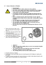
Page 17: ...coupling parts The covering must not touch the coupling and or influence it in its function Remove the fixing screws on the claw ring and push it back Figure 9 Pos 1 Secure the claw ring against uninten tional displacement Cut through the intermediate ring at a connecting part Figure 9 pos 2 Pull out the intermediate ring Start at the cut through connecting part Attention Make sure that the coupli...

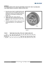
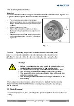
Page 18: ...g see chapter 10 Slightly tighten the screws uniformly Tighten the claw ring threaded joint with the tightening torque MA stipulated in table 8 Fig ure 10 Check the alignment of the coupling according to the specifications in 8 Coupling adjust ment Table 8 Tightening torques MA of the claw ring threaded joint Size 112 128 148 168 194 214 240 265 295 330 370 415 DIN 912 8 8 M8 M8 M10 M10 M10 DIN 91...

Page 19: ...ent If only minor wear or no wear is observed further inspections of the plant can be carried out at regular intervals of 4000 hours however at least once a year if the operating modes and conditions of the plant remain unchanged However should you observe excessive wear on the occasion of this first inspection already check whether the cause for the problem is listed in table 7 Operation faults a...

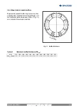
Page 20: ...as the coupling has a distinct torsional backlash or if the minimum buffer thickness PDmin Fig 11 acc to table 9 has been reached Table 9 Minimum buffer thickness PDmin Size 112 128 148 168 194 214 240 265 295 330 370 415 PDmin mm 9 9 10 10 10 10 11 12 13 14 16 17 RINGFEDER TNM GBT TNM GTW BAWN 006 GBR 1 ...

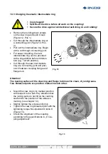
Page 21: ... powder Cut through the new intermediate ring at a connecting joint and posi tion it between coupling flange and flange hub Attention The bearing surface of the claw ring and flange hub must be clean dry and grease free Balanced parts are position marked to each other Mount the claw ring in its marked position with respect to the hub Pay attention that the joining parts do not tilt on the centring...

Page 22: ...214 240 265 295 330 370 415 DIN 933 8 8 8 8 10 10 12 12 12 16 16 16 16 16 MA BS Nm 25 25 49 49 85 85 85 210 210 210 210 210 Warning Before commissioning the plant install all protective devices against unintentional touching of free rotating parts To avoid sparks coverings in stainless steel should be used The coverings must fulfil at least the protection type IP2X The covering is to be so designe...

Page 23: ...01 666 3320 Fax 1 201 664 6053 E mail sales usa ringfeder com HENFEL INDÚSTRIA METALÚRGICA LTDA Av Major Hilário Tavares Pinheiro 3447 CEP 14871 300 Jaboticabal SP Brazil Phone 55 16 3209 3422 E mail vendas henfel com br RINGFEDER POWER TRANSMISSION INDIA PRIVATE LIMITED Plot No 4 Door No 220 Mount Poonamallee Road Kattupakkam Chennai 600 056 India Phone 91 0 44 2679 1411 Fax 91 0 44 2679 1422 E m...

Reviews: