- 18 -
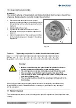
Attention!
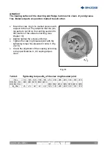
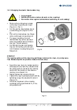
The bearing surface of the claw ring and flange hub must be clean, dry and grease-
free. Balanced parts are position marked to each other.
·
Mount the claw ring in its marked position with
respect to the hub. Pay attention that the join-
ing parts do not tilt on the centring seat and to
the position of the abrasive marking. (see
chapter 10).
·
Slightly tighten the screws uniformly.
·
Tighten the claw ring threaded joint with the
tightening torque M
A
stipulated in table 8 (Fig-
ure 10).
·
Check the alignment of the coupling according
to the specifications in „8 Coupling adjust-
ment”.
Table 8
Tightening torques M
A
of the claw ring threaded joint:
Size
112 128 148 168 194 214 240 265 295 330 370 415
DIN 912- 8.8 M8 M8 M10 M10 M10
DIN 912-10.9
M12 M12 M14 M14 M16 M16 M16
M
A
[Nm]
25
25
49
49
49 125 125 200 200 310 310 310
Fig. 10
RINGFEDER
®
TNM GBT, TNM GTW
BAWN 006-
GBR
-1


