- 22 -
Attention!
The bearing surfaces of the claw ring and flange hub must be clean as well as oil and
grease-free. Balanced parts are position marked to each other.
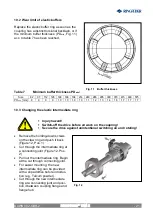
Mount the claw ring into its marked
position. When doing this pay atten-
tion also that the parts not tilt when
being joined to the centering seat.
Tighten the screws slightly.
Tighten up the claw ring threaded
joints with the tightening torque M
A
stipulated in table 8 (Figure 13).
Check the alignment of the coupling
according to “8 Coupling adjust-
ment”.
Table 8
Tightening torques M
A
for the bolting of the claw ring:
Size
82 97 112 128 148 168 194 214 240 265 295 330 370 415 480 575
DIN 912- 8.8
M6 M6 M8 M8 M10 M10 M10
DIN 912-10.9
M12 M12 M14 M14 M16 M16 M16 M20 M20
M
A
[Nm]
10 10 25 25 49 49 49 125 125 200 200 310 310 310 610 610
Observe reduced tightening torques for the bolting of the claw ring if coupling parts
are phosphated and oiled!
Size
82 97 112 128 148 168 194 214 240 265 295 330 370 415 480 575
DIN 912- 8.8
M6 M6 M8 M8 M10 M10 M10
DIN 912-10.9
M12 M12 M14 M14 M16 M16 M16 M20 M20
M
A
[Nm]
8,3 8,3 20 20 40 40 40 100 100 160 160 240 240 240 490 490
Warning!
Before commissioning the plant install all protective devices
against unintentional touching of free rotating parts.
To avoid sparks coverings in stainless steel should be used.
The coverings must fulfil at least the protection type IP2X.
The covering is to be so designed that it does not deposit dust
onto the coupling parts.
The covering must not touch the coupling or influence it in its
functioning.
When using accessories and spare parts which were not originally manufactured
by
RINGFEDER POWER TRANSMISSION
, no liability or guarantee for any
damages will be accepted.
Fig. 13
RINGFEDER
®
TNM E
BAWN 002-GBR-2


