


9
OPERATION
1.
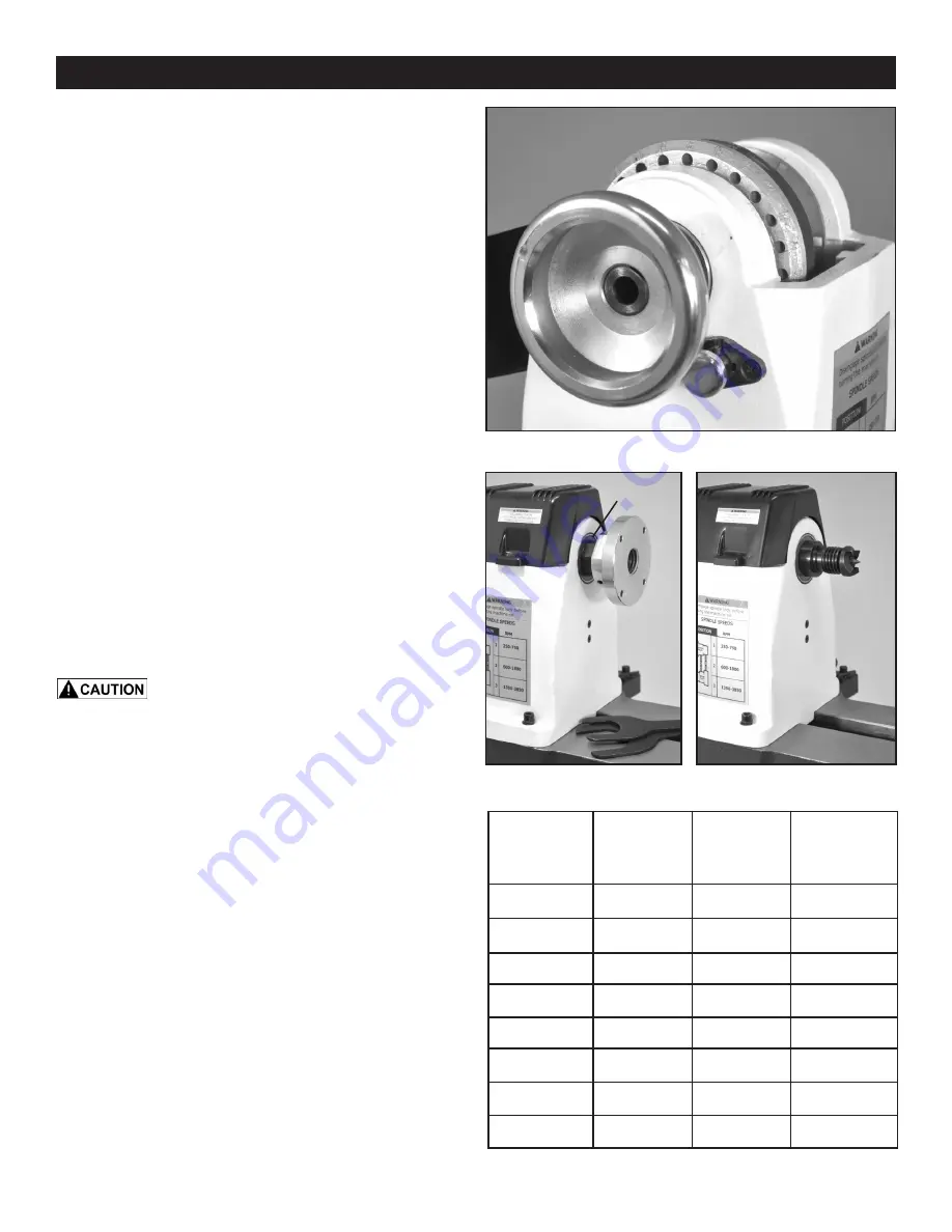
HEADSTOCK SPINDLE LOCK:
The spring loaded
Index Pin Assembly (#44, FIG. 1, A) is primarily used to po-
sition the spindle for making accurate, spaced pattern work
on projects such as straight fluting, grooving, drilling, detail
carving, wood burning patterns and laying out designs. See
page 13 for more information.
The Index Pin will also keep the spindle from turning, so
if necessary, faceplates, chucks or other accessories that
have been mounted on the threaded spindle can be re-
moved.
NOTE:
Do not put excessive pressure on the Index
Pin when trying to remove accessories from the lathe, or
damage to the pin, or spindle pulley, may result.
The Index Pin is spring loaded. Pull the Pin out, so that its
Roll-Pin is removed from the ‘high’ grooves in the Locating
Sleeve. Rotate the pin 90° to position the roll-pin back into
the Sleeve. The deeper groove locations will insert the In-
dex Pin’s shaft into the Spindle pulley’s hole(s), locking the
spindle in place. To unlock the spindle, reverse the process.
FIG. 1
FIG. 3
HEADSTOCK CONTROLS
2.
HEADSTOCK INDEXING HOLES:
(FIG. 1, B) The
largest Spindle Pulley (#52, B) has 24 postioning holes
located around its left side. Each index hole is 15° apart,
and marked for reference around the perimeter of the pul-
ley. Insert the Indexing Pin (A) into one of these holes, and
the spindle will be locked so that work can be done on the
workpiece. See page 13 for additional information.
Never start the lathe with the index pin en-
gaged in the spindle, or damage to the machine will result.
- Never engage the headstock spindle lock while the
spindle is turning, or damage to the lathe will result.
.
3.
HEADSTOCK FACEPLATE:
Faceplates (#58, FIG.
2, A) are used for turning bowls and plates. There are a
number of screw holes on the plate for mounting the work-
piece for turning. Thread the faceplate onto the spindle in
a clockwise direction, and tighten it in place with the set
screws that are located on the back hub of the faceplate.
To remove the faceplate, loosen the set screws. Use one
wrench on the flat portion of the spindle (X) and another
wrench on flats of the faceplate’s rear hub, then loosen the
faceplate from the spindle. Rotate the faceplate counter-
clockwise to fully remove it from the spindle.
4.
HEADSTOCK SPUR CENTER:
The Spur Center (#59,
FIG. 2, B) is used for turning between centers. It fits into
the spindle. Both spindle and the spur center have match-
ing MT-2 tapers. The spur center can be removed from the
spindle with the long Knockout Bar, inserted through the
outboard left end of the spindle. NOTE: Be careful and hold
the spur center during this process so it does not fly out
onto the floor. A short Knockout Bar is supplied to remove
the Spur Center’s Center Point, if it needs replacing.
FIG. 2
DIAMETER
OF WORK
ROUGHING
RPM
GENERAL
CUTTING
RPM
FINISHING
RPM
Under 2”
2 to 4”
4 to 6”
6 to 8”
8 to 10”
10 to 12”
12 to 14”
14 to 16”
1520
750
510
190
220
255
300
380
3200
1600
1080
400
460
540
650
3200
2480
1650
1240
1000
830
710
620
810
A
B
X
A
B


