background image

7

Model 70-220VSR Wood Lathe is shipped complete in one box.

Unpacking and Clean-up

1.  Carefully remove all contents from the shipping carton. Compare the contents with the list of contents to make sure                        

     that all of the items are accounted for, before discarding any packing material. Place parts on a protected surface 

     for easy identification and assembly. If any parts are missing or broken, please call RIKON Customer Service (877-    

     884-5167) as soon as possible for replacements. DO NOT turn your machine ON if any of these items are missing. 

     You may cause injury to yourself or damage to the machine.

2.  Report any shipping damage to your local distributor.
3.  Clean all rust protected surfaces with ordinary household type grease or spot remover.  Do not use flammables; gas-           

     oline, paint thinner, mineral spirits, etc. These may damage painted surfaces. Clean thoroughly under the headstock,                    

     tailstock and tool rest body. Then coat with a light film of dry lubricant spray, or wax, to enhance passage of the tool             

     rest and tailstock on/over the bed. Refrain from using any water-based solvents as they will promote metal rusting.

4.  Apply a coat of paste wax to any machined surfaces to prevent rust. Wipe all parts thoroughly with a clean dry cloth.
5.  Set packing material and shipping carton aside. Do not discard the packing material until the machine has been set up      

     and is running properly, in case a return is necessary.
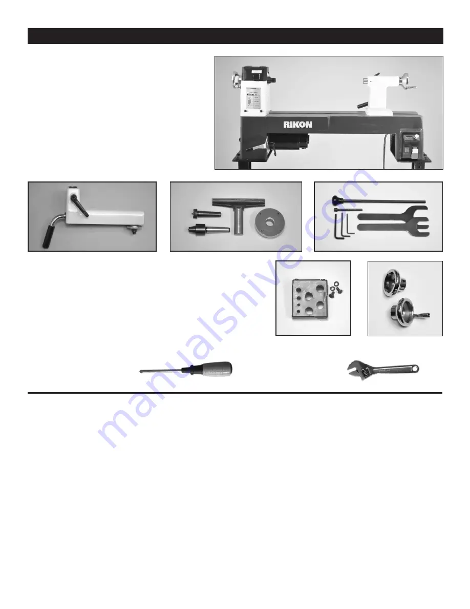
CONTENTS OF PACKAGE

A.  Lathe Bed Assembly - including;


B.  Motor Assembly


C.  Headstock Assembly


D.  Tailstock Assembly


E.  Electronic Controls

CONTENTS OF PACKAGE

LIST OF LOOSE PARTS

F.   Tool Rest Base

G.  Spur Center

H.  Live Center

I.    8” Tool Rest

J.   3” Faceplate

K.  Long Knockout Bar

L.  Short Knockout Bar

M.  Hex Wrenches (3, 4, 5 mm)

N.  Spanner Wrenches (32, 46 mm)

O.  Tool Holder, Screws & Washers (2)

P.   Outboard Hand Wheel

Q.  Tailstock Hand Wheel

R.  Manual & Warranty Card 

      (not shown)


A

E

B

C

F

G

D

H

I

J

L

K

M

N

O

ADDITIONAL TOOLS REQUIRED FOR ASSEMBLY & ADJUSTMENTS

#2 Phillips Screwdriver

Adjustable Wrench

P

NOTE:

 Lathe shown with Outboard Hand Wheel * on the 

Headstock and Tailstock Hand Wheel ** installed.
Lathe is shown on the #70-920 Stand (sold separately)

*

**

Q

Summary of Contents for 70-220VSR

Page 1: ...ual Record the serial number and date of purchase in your manual for future reference Serial Number _________________________ Date of purchase _________________________ For technical support or parts questions email techsupport rikontools com or call toll free at 877 884 5167 4001824 ...

Page 2: ...een Centers 20 508 mm Electronic Variable Speeds 250 3 850 RPM Speed Ranges 3 250 750 550 1 650 1 300 3 850 RPM Spindle Rotation 2 Forward C Clockwise Reverse Clockwise Spindle Nose Threading 1 x 8 TPI Headstock Taper MT 2 Tailstock Taper MT 2 Hole Through Drive Spindle 3 8 10 mm Hole Through Tailstock 3 8 10 mm Tailstock Ram Travel 3 1 2 90 mm Number of Indexing Positions 24 Tool Rest Post Diamet...

Page 3: ...ctrical receptacle The 3rd prong is used to ground the tool and provide protection against accidental electric shock DO NOT remove the 3rd prong See Grounding Instructions on the following pages 4 AVOID A DANGEROUS WORKING ENVIRONMENT DO NOT use electrical tools in a damp environment or expose them to rain 5 DO NOT use electrical tools in the presence of flammable liquids or gasses 6 ALWAYS keep t...

Page 4: ...er cord An undersized cord will cause a drop in line voltage resulting in a loss of power and overheating USE ONLY A 3 WIRE EXTENSION CORD THAT HAS A 3 PRONG GROUNDING PLUG AND A 3 POLE RECEPTACLE THAT ACCEPTS THE TOOL S PLUG 27 ADDITIONAL INFORMATION regarding the safe and proper operation of this product is available from Power Tool Institute 1300 Summer Avenue Cleveland OH 44115 2851 www powert...

Page 5: ...he grounding instructions or if you are not sure the tool is properly grounded when installing or replacing a plug USE ONLY A 3 WIRE EXTENSION CORD THAT HAS THE PROPER TYPE OF A 3 PRONG GROUNDING PLUG THAT MATCHES THE MACHINE S 3 PRONG PLUG AND ALSO THE 3 POLE RECEPTACLE THAT ACCEPTS THE TOOL S PLUG REPLACE A DAMAGED OR WORN CORD IMMEDIATELY This tool is intended for use on a circuit that has an e...

Page 6: ...occurs stop the lathe to check the workpiece settings between centers or on face plates 21 For sanding or applying finishes remove the tool rest from the machine Use low speeds to avoid heat build up 22 Do not engage the spindle lock when the lathe is turning and be sure to disengage the spindle lock when done working to avoid damage to the machine next time the lathe is turned on 23 Never stop th...

Page 7: ...ax to enhance passage of the tool rest and tailstock on over the bed Refrain from using any water based solvents as they will promote metal rusting 4 Apply a coat of paste wax to any machined surfaces to prevent rust Wipe all parts thoroughly with a clean dry cloth 5 Set packing material and shipping carton aside Do not discard the packing material until the machine has been set up and is running ...

Page 8: ...e J Tool Rest Base Locking Lever K Live Center L TailstockAssembly M Face Plate N Electronic Controls ON OFF Switch Forward Reverse Switch Speed Control Knob Digital Speed Readout O Lathe Bed P Power Cord Q Tailstock Locking Lever R Tailstock Hand Wheel S Tailstock Locking Handle T Tool Holder Tools E F J MOVING INSTALLING THE LATHE 5 Install the 8 Tool Rest into the Tool Rest Base 6 The Faceplate...

Page 9: ...r additional information Never start the lathe with the index pin en gaged in the spindle or damage to the machine will result Never engage the headstock spindle lock while the spindle is turning or damage to the lathe will result 3 HEADSTOCK FACEPLATE Faceplates 58 FIG 2 A are used for turning bowls and plates There are a number of screw holes on the plate for mounting the work piece for turning ...

Page 10: ...dle to adjust the tool rest at a specific angle or height Tighten handle when properly positioned 1 TAILSTOCK LOCK HANDLE FIG 5 D Locks the tailstock in position along the length of the lathe bed Unlock handle to position the tool rest to move the tail stock Tighten handle when properly positioned 2 TAILSTOCK QUILL LOCK HANDLE E Secures the tailstock quill in position Unlock the handle to move the...

Page 11: ...ed in step 3 above 5 Close the Headstock Cover and Bed Cover Plate Door to protect the belt pulleys and internal working from dust FIG 7 FIG 8 CHANGING BELT SPEEDS THE MACHINE MUST NOT BE PLUGGED IN AND THE POWER SWITCH MUST BE IN THE OFF POSITION UNTIL ALL ADJUSTMENTS ARE COMPLETE ADJUSTING THE LOCKING HANDLES The locking handles on the tailstock and tool rest are pre set at the factory to give a...

Page 12: ... of the other in both of the two 2 threaded holes This stacking keeps the set screws from loosening during use 9 Remove the Retaining C Clip 39 that is on the out side left end of the spindle where the hand wheel was 10 Carefully knock the spindle towards the tailstock Use a block of wood against the spindle end to prevent any damage when it is hit with a mallet hammer The spindle pulley now loose...

Page 13: ...ojects such as straight fluting grooving drilling detail carving wood burning patterns laying out designs and more The Indexing Chart FIG 12 shows how to rotate the spindle to access any of the 24 indexing holes The 8 pri mary settings are listed in FIG 13 however other indexing design settings are possible Vary the index combinations to make non equal spaced patterns Also by rotating re postionin...

Page 14: ...SHOOTING Electronic Speed Control ACTION CODES 01 02 03 05 06 07 08 10 CODE CONDITION ACTION Hardware Protection Mode Possible damage to the electronic controller Software Protection Mode Possible damage to the electronic controller Low Voltage Abnormality Protection Mode Voltage is lower than 85V Sensor Problem There is no signal from the speed sensor After 1 minute the error code will be changed...

Page 15: ... tools 2 Tool rest is set too low 3 Tool rest is set too far from the workpiece 4 Improper turning tool is being used 1 Sharpen the tools 2 Reposition the tool rest height 3 Set the tool rest closer to the workpiece 4 Use the correct tool for operation 1 Excessive pressure being applied by the tailstock onto the workpiece 2 Tailstock is not secured in place 3 Lathe bed and tailstock mating surface...

Page 16: ...lling for Replacement Parts For Parts under Warranty the Serial Number of your machine is required 71 18A 18B 48C 70B 70A 15 1 4 3 2 5 7 8 9 10 11 16 19 20 21 22 18 17 6 14 12 13 23 67 68 69 72 73 74 75 76 77 78 79 80 81 82 83 84 24 25 26 27 28 29 30 31 32 70 220VSR BED ASSEMBLY ...

Page 17: ...xagon socket cap screw Flat washer Lock washer Tool holder Cross pan head screw Countersunk head screw Bed cover plate door Countersunk head screw Magnet Nut Half Countersunk head screw Plate Motor pulley Socket head cap screw Poly v belt Hex socket cap screw Lock washer Self locking nut Cross pan head screw Motor connecting plate Big washer Locking handle Motor Hex socket cap screw Retaining ring...

Page 18: ...t Number when calling for Replacement Parts For Parts under Warranty the Serial Number of your machine is required 34A 33A 34B 48A 48B 48C 48D 48E 48F 33B 51 51A 35 36 37 38 39 40 41 33 44 45 46 47 48 50 52 53 54 55 56 57 40 58 59 49 70 220VSR HEADSTOCK ASSEMBLY ...

Page 19: ...screw M4X10 Screw Cross pan head screw Hinge Flat washer Headstock cover Hinge shaft Wave washer Bearing Retaining ring Socket head cap screw Hand wheel Roll pin not shown part of 44 Index pin knob shaft not shown ref 44 Index pin assembly Spring Split washer Tapping screw Support bracket Threaded plate Cylinder head hex socket bolt Cable plate Cross pan head screw Flat washer Plate Sensor module ...

Page 20: ...1S 2 JMWL1203091000B 1 HY12 6P 01 1 JMWL1203090008 1 JMWL1203090100B 1 JMWL1203090005 P70 220VSR 64A1 1 JMWL1203090001 001S 1 HY18 32A Tapping screw Plastic electric box cover M20 Pull off M16 Pull off Plastic electric box Control box assembly Switch FWD REV Digital readout Actuator Speed control knob Speed control assembly Switch box cover Key switch assembly DESCRIPTION KEY NO 60 61 62B 62C 63 6...

Page 21: ...ght end of the 70 220VSR Midi Lathe to extend the lathe s working spindle length capacity to 44 Universal all steel Stand Extension bolts onto the 70 910 and 70 920 stands to support lathes with Bed Extensions The stand ex tension adjusts from 18 3 4 to 32 1 4 long and 24 1 2 to 34 1 2 working height ADDITIONAL LATHE ACCESSORIES For additional lathe accessories or replacement parts contact your lo...

Page 22: ...22 NOTES Use this section to record Maintenance Service and any calls to Technical Support ...

Page 23: ... or educational purposes This limited warranty does not apply to accessory items such as blades drill bits sanding discs grinding wheels belts ball bearings and other related items Seller shall in no event be liable for death injuries to persons or property or for incidental contingent special or consequential damages arising from the use of our products T To take advantage of this warranty proof ...

Page 24: ...www rikontools com 70 220VSRM6 70 220VSR For more information 16 Progress Road Billerica MA 01821 877 884 5167 978 528 5380 techsupport rikontools com ...

Reviews: