


13
ADJUSTMENTS
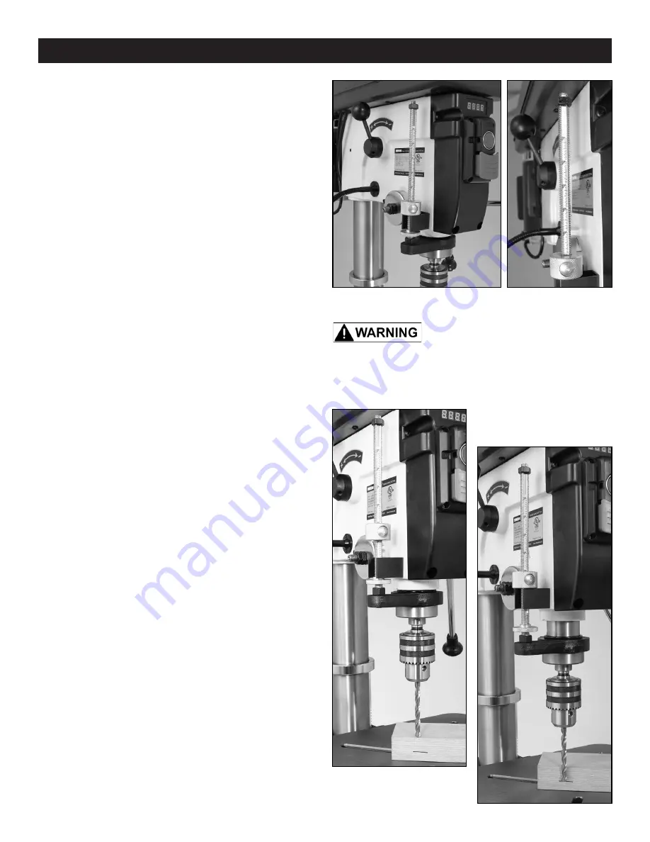
ADJUSTING THE DEPTH STOP
The Depth Stop is used for boring multiple holes at
the same, identical depth. The threaded rod includes
a scale and a large quick release nut for fast setting of
the depth that the spindle/chuck will travel. FIG. 17.
The chuck’s travel distance/depth is read on the scale
at the top of the Depth Setting Nut (#16 on Parts
Diagram D). At reading ‘0’, the Depth Setting Nut
should be down on top of the Depth Plate (#58 on
Diagram B). FIG. 17.
Setting the a specific depth can be done in 2 ways:
THE DEPTH SCALE METHOD
1. With your workpiece on the table, raise the table
until the surface of the workpiece touches the drill bit
that is in the chuck. Lock the table in position.
2. Adjust the Depth Setting Nut to the desired depth
on the threaded rod’s scale. The Depth Nut has a
quick release button for fast moving of the nut.
NOTE:
Depth is read at the TOP of the nut. The
Depth Nut can also be rotated for fine depth
adjustments. FIG. 18.
3. Drill a test hole to check the depth setting, and
adjust the depth setting as necessary. It is best to
use a scrap piece of wood, that is the exact same
thickness of your workpiece, for test drilling to ensure
the proper results.
THE WORKPIECE METHOD
1. Mark a line on the side of a workpiece at the
desired depth needed.
2. Lower the drill bit that is in the chuck along the side
of the workpiece, until it aligns with the drawn line.
NOTE:
The machine must be OFF for this procedure.
3. Holding the drill bit at the desired depth, lower
the Depth Setting Nut until it rests down on the metal
Depth Plate. The drilling depth is now set.
4. Drill a test hole to check the depth setting, and
adjust as necessary. It is best to use a scrap piece of
wood that is the exact same thickness of your work-
piece for test drilling, to ensure the proper results.
FIG. 17
FIG. 18
FIG. 19
THE MACHINE MUST NOT BE
PLUGGED IN AND THE POWER SWITCH MUST BE IN
THE OFF POSITION UNTIL ALL ADJUSTMENTS ARE
COMPLETE.


