Rikon Power Tools 30-212VS Operator'S Manual Download Page 3

3

SAFETY SYMBOLS

IMPORTANT!

 Safety is the single most important consideration in the operation of this equipment. 

The following 

instructions must be followed at all times. 

Failure to follow all instructions listed below may result in electric shock,

fire, and/or serious personal injury.  

There are certain applications for which this tool was designed. We strongly recommend that this tool not be modified

and/or used for any other application other than that for which it was designed. If you have any questions about its

application, do not use the tool until you have contacted us and we have advised you.

SAFETY INSTRUCTIONS


GENERAL SAFETY 

KNOW YOUR POWER TOOL. 

Read the owner’s manual 

carefully. Learn the tool’s applications, work capabilities, 

and its specific potential hazards.

BEFORE USING YOUR MACHINE

To avoid serious injury and damage to the tool, read and 

follow all of the Safety and Operating Instructions before 

operating the machine.

1.  Some dust created by using power tools contains 

chemicals known to the State of California to cause cancer, 

birth defects, or other reproductive harm.

Some examples of these chemicals are:

•  Lead from lead-based paints.

•  Crystalline silica from bricks, cement, and other 

•  masonry products.

•  Arsenic and chromium from  chemically treated lumber.

Your risk from these exposures varies, depending on how 

often you do this type of work. To reduce your exposure to 

these chemicals: work in a well ventilated area and work 

with approved safety equipment, such as those dust masks 

that are specially designed to filter out microscopic 

particles.

2.  

READ 

the entire Owner’s Manual. 

LEARN

 how to use 

the tool for its intended applications.

3.  

GROUND ALL TOOLS.

 If the tool is supplied with a 3 

prong plug, it must be plugged into a 3-contact electrical 

receptacle. The 3rd prong is used to ground the tool and 

provide protection against accidental electric shock. 

DO 

NOT 

remove the 3rd prong. See Grounding Instructions 

on the following pages.

4.  

AVOID A DANGEROUS WORKING ENVIRONMENT. 

DO NOT

 use electrical tools in a damp environment or 

expose them to rain.

5.  

DO NOT

 use electrical tools in the presence of 

flammable liquids or gasses.

6.  

ALWAYS

 keep the work area clean, well lit, and 

organized. 

DO NOT

 work in an environment with floor 

surfaces that are slippery from debris, grease, and wax.

7.  

KEEP VISITORS AND CHILDREN AWAY.


DO NOT 

permit people to be in the immediate work area, 

especially when the electrical tool is operating.

8.  

DO NOT FORCE THE TOOL

 to perform an operation 

for which it was not designed. It will do a safer and 

higher quality job by only performing operations for 

which the tool was intended.

9.  

WEAR PROPER CLOTHING. DO NOT

 wear loose 

clothing, gloves, neckties, or jewelry. These items can 

get caught in the machine during operations and pull the 

operator into the moving parts. The user must wear a 

protective cover on their hair, if the hair is long, to 

prevent it from contacting any moving parts.

10.  

CHILDPROOF THE WORKSHOP AREA

 by 

removing switch keys, unplugging tools from the 

electrical receptacles, and using padlocks.

11.  

ALWAYS UNPLUG THE TOOL FROM THE 

ELECTRICAL RECEPTACLE

 when making adjustments, 

changing parts or performing any maintenance.


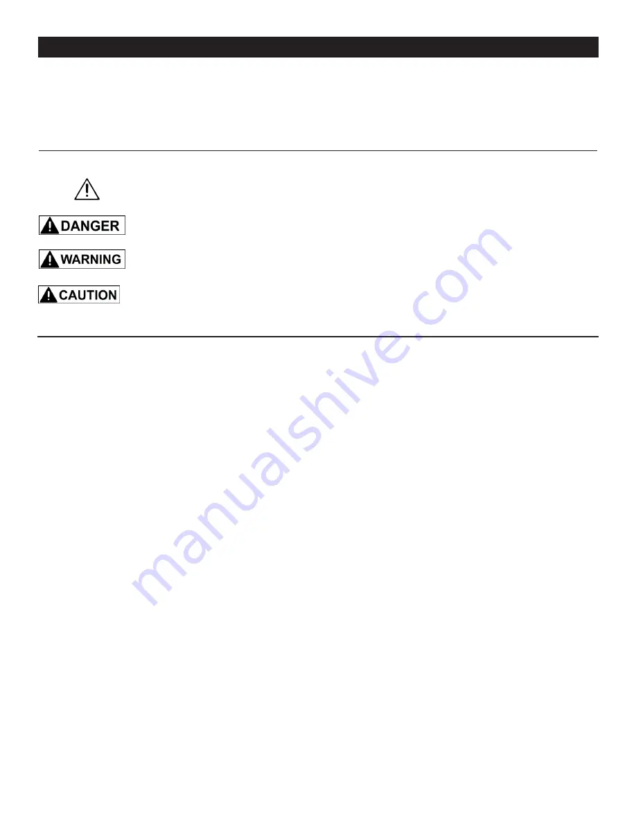
SAFETY ALERT SYMBOL: Indicates DANGER, WARNING, or CAUTION. This symbol may be used 

                          in conjunction with other symbols or pictographs.


       Indicates an imminently hazardous situation, which, if not avoided, could result in death or


       serious injury.


       Indicates a potentially hazardous situation, which, if not avoided, could result in death or serious 


       injury.


       Indicates a potentially hazardous situation, which, if not avoided, could result in minor or


       moderate injury.

             NOTICE:


Shown without Safety Alert Symbol indicates a situation that may result in property damage.

Summary of Contents for 30-212VS

Page 1: ...f purchase in your manual for future reference Serial Number _________________________ Date of purchase _________________________ For technical support or parts questions email techsupport rikontools...

Page 2: ...300mm Chuck Size 1 32 5 8 0 8 16mm Chuck Taper JT33 Drilling Capacity 1 25 4mm Spindle Travel 3 5 32 80mm Spindle Taper MT2 Head Rotates 360 Speed Range RPM Variable 150 700 600 2 800 Quill Diameter...

Page 3: ...trical receptacle The 3rd prong is used to ground the tool and provide protection against accidental electric shock DO NOT remove the 3rd prong See Grounding Instructions on the following pages 4 AVOI...

Page 4: ...cord will cause a drop in line voltage resulting in a loss of power and overheating USE ONLY A 3 WIRE EXTENSION CORD THAT HAS A 3 PRONG GROUNDING PLUG AND A 3 POLE RECEPTACLE THAT ACCEPTS THE TOOL S P...

Page 5: ...the grounding instructions or if you are not sure the tool is properly grounded when installing or replacing a plug USE ONLY A 3 WIRE EXTENSION CORD THAT HAS THE PROPER TYPE OF A 3 PRONG GROUNDING PL...

Page 6: ...ys clear the table and work area before turning on the Drill Press 6 Always use drill bits cutting tools and accessories with a 1 2 shank or less 7 Never place hands near the drill bit cutting tool or...

Page 7: ...al distributor Take photographs for any possible insurance claims 3 Clean all rust protected surfaces with ordinary house hold type grease or spot remover Do not use gasoline paint thinner mineral spi...

Page 8: ...move or carry the Drill Press with the work table chuck or operating handles as this may also damage the machine 2 Secure the machine onto a solid stand or bench that is located in an area that has a...

Page 9: ...through the un threaded hole on the bracket casting The handle will engage the threading on the other side of the hole in the casting then tighten the locking lever to secure the bracket in place on t...

Page 10: ...es in the Handle Seat 86 Use the 8mm end of the Special Wrench 131 to secure the handles in place FIG 7 NOTE Figures 6 7 also show the motor Lock Knobs 67 C Tension Lever 89 D and the motor Mount Asse...

Page 11: ...press spindle s tapered hole Make sure to align the flat part of the arbor with the slot in the spindle FIG 10 3 Open the jaws of the chuck until the 3 jaws are completely hidden inside of the chuck...

Page 12: ...cation you need Then re tighten the set screws and lever to secure the parts in the new position on the column 5 TO TILT THE TABLE on an angle the table and support arm assembly move together Loosen t...

Page 13: ...t the depth setting as necessary It is best to use a scrap piece of wood that is the exact same thickness of your workpiece for test drilling to ensure the proper results NOTE See page 17 for instruct...

Page 14: ...ed Move the lever BACKWARD for slower speeds This Drill Press has two variable speed ranges from 150 to 700 and 600 to 2 800 RPM To change from one speed range to the other only the rear Drive V Belt...

Page 15: ...increased to the desired speed for the particular drilling job or material being worked by rotating the Speed Control Handle on the left side of the head 2 Before turning the drill press OFF it is rec...

Page 16: ...view them directly with optical instruments Do not disassemble or modify the lasers Do not operate lasers around children Turn off lasers when not in use 1 Prepare your drill press for drilling The t...

Page 17: ...ty of factors a the workpiece material hardness wood composites plastics or metal b the size of hole diameter c the depth of the hole d the type of drill bit or other cutter needed to make the desired...

Page 18: ...1 5 8 2 500 250 NR 160 250 NR 2 1 8 2 1 2 250 NR NR 160 250 NR 2 5 8 3 100 NR NR 100 100 NR CIRCLE CUTTERS 1 1 2 3 500 250 250 NR NR NR 3 1 4 6 250 250 250 NR NR NR Consult the drill bit manufacturer...

Page 19: ...oil on all of the internal surfaces 7 Apply 2 tube grease to the worm gears in the table elevation mechanism and rack to keep them operating smoothly 8 The ball bearings in the spindle and pulley asse...

Page 20: ...1 Machine is not plugged in 2 Low line voltage 3 Loose connection 4 Defective switch 5 Defective motor capacitor 6 Starting at highest RPM speed position 1 Plug in machine 2 Check fuses or reset circu...

Page 21: ...feed speed 5 Lubricate bit Make sure bit and flutes are clean of rust resin build up etc Quill returns too slow or too fast 1 Spindle return spring has improper tension 1 Adjust spindle return spring...

Page 22: ...22 PARTS DIAGRAM 30 212VS 12 Drill Press NOTE Please reference the Manufacturer s Part Number when calling for Replacement Parts For Parts under Warranty the Serial Number of your machine is required...

Page 23: ...Quill Set Screw M8 1 2 3 4 5 6 7 8 9 10 11 12 13 14 15 16 17 18 19 20 21 22 23 24 25 26 27 28 29 30 31 32 33 34 35 36 37 38 39 40 41 42 43 44 45 46 P30 212VS 1 P30 212VS 2 P30 212VS 3 P30 212VS 4 P30...

Page 24: ...57 58 59 60 61 62 63 64 65 66 67 68 69 70 71 72 73 74 75 76 77 78 79 80 81 82 83 84 85 86 87 88 89 90 91 92 93 P30 212VS 47 P30 212VS 48 P30 212VS 49 P30 212VS 50 P30 212VS 51 P30 212VS 52 P30 212VS...

Page 25: ...94 95 96 97 98 99 100 101 102 103 104 105 106 107 108 109 110 111 112 113 114 115 116 117 118 119 120 121 122 123 124 125 126 127 128 129 130 131 131A 132 133 134 135 136 137 138 139 140 P30 212VS 94...

Page 26: ...26 NOTES Use this section to record maintenance service and any calls to Technical Support...

Page 27: ...anty may not be transferred This warranty does not apply to defects due directly or indirectly to misuse abuse negligence accidents repairs alterations lack of maintenance or normal wear and tear Unde...

Page 28: ...www rikontools com 30 212VSM1 30 212VS For more information 16 Progress Road Billerica MA 01821 877 884 5167 978 528 5380 techsupport rikontools com...

Reviews: