


19
MAINTENANCE
Turn the power switch “OFF” and disconnect the plug from the outlet prior to adjusting
or maintaining the machine. DO NOT attempt to repair or maintain the electrical components of the motor.
Contact a qualified service technician for this type of maintenance.
1. Before each use:
- Check the power cord and plug for any wear or
damage.
- Check for any loose screws, hardware or parts.
- Check the area to make sure it is clear of any
misplaced tools, lumber, cleaning supplies, etc. that
could hamper the safe operation of the machine.
2. To avoid a build-up of wood dust, regularly clean
all parts of the machine using a soft cloth, brush or
compressed air. A general cleaning should be done
after every use to avoid future problems and ensure
the machine is in ready condition for its next use.
WARNING:
If blowing sawdust, wear proper eye pro-
tection to prevent debris from blowing into eyes.
3. Keep the machined surfaces of the drill press table
and base free of resin and rust. Clean them regularly
with a non-flammable solvent, then coat with a light
film of dry lubricant spray or wax.
4. Lubricate the table bracket and locking lever bolts
to keep them operating smoothly.
5. Clean the column on a regular basis to prevent
the build-up of dust, drilling residue and rust. Treat
the posts with a dry lubricant spray or a light coating
of wax. Do not use ordinary oil which will collect dust
and hamper the movement of parts along the column.
6. Periodically, lower the quill assembly and apply
a light coating of machine oil to the quill and spindle
surfaces. Raise and lower the quill a few times to
distribute the oil on all of the internal surfaces.
7. Apply #2 tube grease to the worm gears in the
table elevation mechanism and rack to keep them
operating smoothly.
8. The ball bearings in the spindle and pulley assem-
blies are lifetime lubricated, sealed, and do not need
any further care.
9. Keep the drive belt and pulley surfaces free of oil
and grease. Periodically, check the drive belt for wear
and replace if necessary.
CHANGING THE DRIVE BELT
1. Turn on the drill press and adjust the spindle
speed to the highest speed setting, in either the
low range 700 RPM or the high range 2,800 RPM.
This sets the gear plates high up on their spindles.
See page 14 for Adjusting Drill Speeds.
2. Turn the machine OFF and disconnect it from
the power source.
3. Loosen the belt tension by moving the motor
closer to the head casting. Loosen the two Lock
Knobs (#67) and with 16mm wrench turn the motor
plate’s leveling Bolt (#137) clockwise towards the
motor. Then pull the
Tension Lever (#89) forward to
shift the motor mount assembly forward.
4. Open the top lid to access the drive belts.
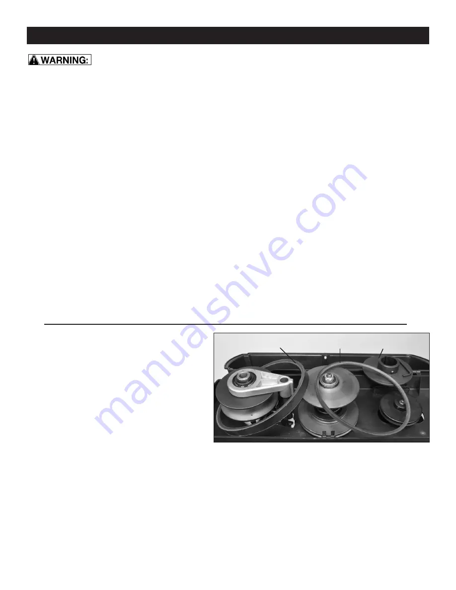
Remove the large, front V-Belt (#106, Fig. 28, A).
This is done by first removing the top, Moveable
Pulley (#114, B) from the center Pulley Shaft
(#100). Loosen the Hex Screw (#115) on the pulley,
and lift the pulley off of the shaft.
FIG. 28
5. Work the front, large drive belt (A) up and off of the
center shaft and lay it aside to re-install later.
6. Remove the rear Drive V-Belt (#80, Fig. 28, C)
from the rear pulley and center shaft.
7. Replace the belts by reversing the process.
NOTE:
When replacing the top, center pulley, make
sure to align the key way with the key (#103) on the
pulley shaft. Push the motor pulley down with 2 hands
to compress the lower spring (#112) and position
the pulley down on the shaft as far as possible, then
tighten the hex screw to secure it in position.
B
A
C


