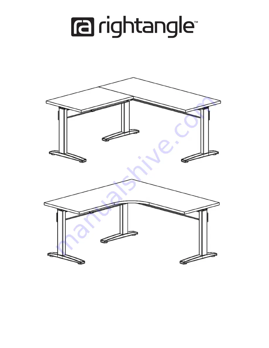
NewHeights™ Series 4 Bonita ET 3-Leg Workstation
Warranty: raproducts.com/warranty
Instruction #54022 • Dated: 02/21/2019
1 of 12
Page 1: ...NewHeights Series 4 Bonita ET 3 Leg Workstation Warranty raproducts com warranty Instruction 54022 Dated 02 21 2019 1 of 12 ...
Page 2: ...HE MANUFACTURER 2 Electrical Height Adjustment The height of this Product may be adjusted electronically Contact with electrical voltage may cause serious injury and death Only use the Product in compliance with these instructions This Product should not be used in environments with high levels of humidity or moisture KEEP CORDS AND ELECTRICAL COMPONENTS AWAY FROM HEAT AND LIQUIDS DO NOT OPEN ANY ...
Page 3: ...put hole Left leg has nuts for motor mount Legs must be in their lowest position before installation Tools Required for Assembly A Power Driver with Adjustable Torque B Tape Measure C 2 Phillips Head Driver Bit D 2 Square Head Drive Bit Recommended A B C D Hardware and Tools Included for Assembly may have extra E F G H I J K L M N 0 Bonita Parts P Cross Support x2 Q U Channel x2 R Long Hex Rod x1 ...
Page 4: ...8 screws are provided If your worksurface is 5 8 or thinner you will need to supply your own hardware 3 00 Step 1 A W O Insert the hex rod through the motor assembly and into the left leg drive input hole Turn the hex rod clockwise 1 6 or 1 3 of a turn with an adjust able wrench if it is not aligned properly with the drive input The hex rod should slide all of the way into the leg Tighten motor mo...
Page 5: ...or 1 3 of a turn with an adjustable wrench if it is not aligned properly with the drive input The hex rod should slide all of the way into the leg Step 2 Step 3 Slide the cross support over the right leg cross support bracket Place the corner bracket as shown and slide the cross support over it Install the bolts and washers and tighten them Corner bracket J K J K N ...
Page 6: ...rod into the left leg drive hole Rotate the entire motor hex assembly until it is aligned with the leg and insert it fully into the hole Step 4 F G M Step 5 Tighten motor mounting bolts after hex rod is installed Legs must be in lowest position before installing hex rod Motor Assembly Short Hex Rod W V Z R F G W Motor Assembly V ...
Page 7: ... and the corner bracket Install the bolts and washers and tighten them J K J K N Align the assembled base with the predrilled pilot holes Screw the base in place with the wood screws Do not over tighten Align the U Channels with the predrilled pilot holes Attach the U Channels to the worksurface using the wood screws Step 7 E A E D ...
Page 8: ...ox and the two J Channel wire management E A E D H E H H Step 9 Note if you have a programmable switch shown please refer to the installation instructions included with the switch Optional Programmable Switch Switch Table will NOT operate unless the control box is screwed tight into the table without any play ...
Page 9: ...Motor Cable Motor Cable Switch Cable For the safety of the user and the workstation the control box contains an internal sensor that is sensitive to movement vibration and collision For faultless operation ensure all cables electronics and accessories are cable managed and secured Excessive load or weight must be distributed evenly Failure to follow these guidelines may cause intermittent function...
Page 10: ...r a musical tone Rapidly press 2 times A musical tone plays two times To add the upper container stop press A musical tone plays two times To add the lower container stop press A musical tone plays two times Remove Container Stops Move the table to the upper or lower preset height Rapidly press 4 times You will hear a musical tone Rapidly press 2 times A musical tone plays two times To delete the ...
Page 11: ...kstation is ready for use If the table is not functioning normally or has lost power perform the reset procedure Reset Procedure Unplug the unit from the wall for 10 seconds Clear all obstructions from the travel path of the desk Plug the unit back in the wall Press and hold the down arrow key until the table reaches its lowest position See Packaged Instructions for Programmable Options Optional P...
Page 12: ...on 2 Quickly press UP UP UP UP to enter the menu mode 3 P01 is displayed and you will hear a musical tone 4 Press the to navigate the menu 5 Navigate to the P09 display 6 Press the button to enter or accept 7 Press and hold the until the workstation has reached its lowest possible position The workstation is now ready to operate Reset Method C 2 Button Switch 1 Clear all obstructions from the trav...