background image

44 |

P a g e

R i g e l M e d i c a l U n i - T h e r m u s e r M a n u a l V 1 . 0

Max Amps at

15sec On / 15sec Off 50% duty cycle

5 - 5115 ohms

0.00

1.00

2.00

3.00

4.00

5.00

6.00

7.00

1

10

100

1000

10000

Ohms

A

m

p

s

rm

s

Max Amps at

60sec On / 15sec Off duty cycle

5 - 100 ohms

0.00

0.50

1.00

1.50

2.00

2.50

3.00

3.50

4.00

4.50

5.00

5

15

25

35

45

55

65

75

85

95

Ohms

A

m

p

s

rm

s

Summary of Contents for Uni-Therm

Page 1: ...Uni THERM Innovating Together Electrosurgical Analyser Copyright 2012 SEAWARD GROUP Last Update 5th July 2012 Instruction Manual 398A550 Revision 1 0 ...

Page 2: ...tems returned for calibration outside of the 13 month period stated above may not be eligible for the second 12 month section of warranty The second 12 month section of the warranty begins at the expiry of the initial 12 month period not when the unit is calibrated Details correct at time of going to print The manufacturer retains the right to make amendments to the above terms and conditions with...

Page 3: ...nt from the SEAWARD GROUP This also applies to accompanying drawings and diagrams Due to a policy of continuous development the SEAWARD GROUP reserves the right to alter the equipment specification and description outlined in this publication without prior notice and no part of this publication shall be deemed to be part of any contract for the equipment unless specifically referred to as an inclu...

Page 4: ...ective 2002 96 EC Please familiarise yourself with the appropriate local separate collection system for electrical and electronic products or contact your local supplier for further information Please dispose of this product according to local regulations Do not dispose of this product along with normal waste material By offering your old products for recycling you will help prevent potential nega...

Page 5: ... 61010 1 2010 Safety requirements for electrical equipment for measurement control and laboratory use Part 1 General requirements BS EN 61326 2006 Electrical equipment for measurement control and laboratory use EMC requirements Performance The instrument operates within specification when used under the conditions in the above standards EMC and Safety Standards The product identified above conform...

Page 6: ...ing a test sequence 21 4 Data 23 4 1 View Data 23 4 2 Transfer Data 24 4 3 Download data 25 4 4 Upload data 26 4 5 Import power reference curves 27 4 6 Transfer test sequences 27 5 Bluetooth Favourites 29 6 Setup 31 6 1 Test sequence 31 6 2 Time Date 36 6 3 Language 36 6 4 Factory restore 37 6 5 About 38 7 Maintaining the Rigel Uni Therm 39 7 1 Cleaning the Analyser 39 7 2 User Maintenance 39 7 3 ...

Page 7: ...i Therm can be carried out in the setup see chapter 6 Analyser Functions The Rigel Uni Therm is able to measure the following parameters both automatically and manually Power Test W mA rms V peak and crest factor HF Leakage mA rms Plate Security REM Remote Electrode Monitoring For the power test an internal array of resistors provide a safe variable load of 0 5115Ω in 5Ω steps enabling the product...

Page 8: ...ometer range up to 475Ω in 1 Ω steps with high and low alarms Stand alone Not relying on PC or laptop Stylish and rugged enclosure with small footprint ideal for in situ testing Graphic colour user interface for fast and easy navigation and connection to DUT Future upgrade ready download future upgrades from the web into your tester Unpacking the Uni Therm Carefully unpack all items from the box a...

Page 9: ... 70 C as is permitted under the IEC 61010 design requirements Do not connect any active power electrodes to the front panel of the Rigel Uni Therm Failure to comply with this will void the warranty and might lead to internal damage of circuits Safety Notes The Rigel Uni Therm Electrosurgical Analyser is designed for use by adequately trained technical personnel only The Rigel Uni Therm Electrosurg...

Page 10: ...e r m u s e r M a n u a l V 1 0 Uni Therm Overview 1 ON OFF button 2 Function keys F1 F4 3 Start Confirm key Green 4 Rotary encoder main navigation key 5 Front panel connections 6 Colour screen 7 Stop Cancel key Red 8 Hinged feet 1 8 6 2 3 4 5 7 ...

Page 11: ... provides an 10kV isolated waveform monitoring output however the scope output is not calibrated 1 REM output connection Black 2 CUT footswitch control output Yellow 3 COAG footswitch control output Blue 1 Variable load bank connections Red Black 2 Oscilloscope output 3 Measuring Device connections White 4 HF Leakage connections 1 2 3 ...

Page 12: ... under test 1 1 Connecting your Analyser Elevate the Rigel Uni Therm on its two hinged feet at the front base Ensure none of the large base and rear ventilation inlets are obstructed during operation 1 2 Rear panel Connect the mains cable to the IEC connector on the rear panel 1 3 Front connection panel For automatic control during HF leakage and Power tests connect the ESU footswitch COAG and CUT...

Page 13: ...ndices A and B for embedded connection diagrams Connect the ESU active and neutral electrodes to the side panel as indicated also fit jumper links positions 1 2 3 4 as required to complete circuits NB each connection diagram has a unique reference code eg 1112 for identification 1 5 Home screen Upon power up of the Rigel Uni Therm the display will be showing the HOMESCREEN ON OFF F1 F2 F3 F4 ...

Page 14: ...REM test HF Leakage Power Test 2 1 Plate Security REM test This test will control a motor driven potentiometer to trigger the neutral patient plate alarm on electrosurgical generators by simulating fault conditions ie resistance too high or too low a variation in resistance etc The variable resistance 0 475 Ω is connected to the two black connectors on the front panel Select the REM test from the ...

Page 15: ...ss the Green button to start the test for automatic mode only Then capture the alarm value by pressing the dedicated Capture Alarm key on the screen In MANUAL UP and DOWN mode the rotary encoder is used to directly control the potentiometer The alarm value is then captured by pressing the dedicated Capture Alarm key on the screen 2 2 HF Leakage The HF Leakage test measures the HF leakage current i...

Page 16: ...g the leakage test with a maximum ON time of 15 seconds To increase the ON TIME the OFF TIME must be increased first in order to remain within the duty cycle limits This is done to protect the EUT from overheating If the selected ON OFF time is above the 50 duty cycle the Uni Therm will calculate this automatically the duty cycle factor appears in red It s not possible to continue without reducing...

Page 17: ...coder to change the settings Press the rotary encoder again to confirm Return to the DIAGRAM mode by using the SHOW DIAGRAM fast key Start the test by pressing the RUN button and confirm with the green START button on the front of the Uni Therm The Rigel Uni Therm could display the following details after the test Press the HOLD key to freeze the reading on the screen The test can be aborted by pr...

Page 18: ...s resolution The Rigel Uni Therm will control the EUT by using the internal footswitch controller Select Power test from the home screen CONT or GRAPH mode using the fast keys and select either the Continuous Graph or External Load test Use the rotary encoder or the dedicated function keys to navigate 2 3 1 Continuous mode The continuous mode allows the user to monitor the power characteristics un...

Page 19: ...and COAG CUT settings determine the type of connection diagrams when the SHOW DIAGRAM button is pressed The COAG CUT settings also determine the activation of the foot paddle control on the front of the Uni Therm Note the duty cycle is limited to 50 or less when the high duty cycle box is un ticked to protect the EUT from overheating It is however possible to obtain up to 60 seconds on time For th...

Page 20: ... generators operating in a soft start mode END LOAD will set the highest resistance at which the power curve measurement is carried out TEST POINTS determines the number of test points resolution of the power distribution graph The higher the number the more detailed the power distribution graphs The TEST TIME will display the total test time of the leakage test and dictate the amount of tests don...

Page 21: ...lly detect of the current graph meets the criteria of the reference graph A full description of how to create a power reference graph is provided in Appendix D 2 3 3 External Load mode The external load mode allows the user to monitor the power characteristics under a specific load condition utilising external loads or under short circuit condition i e for calibration purpose During the test the E...

Page 22: ... in a soft start mode The TEST TIME will display the total test time of the leakage test and dictate the amount of tests done as a result of the selected ON TIME and OFF TIME The BIPOLAR MONO POLAR and COAG CUT settings determine the type of connection diagrams when the SHOW DIAGRAM button is pressed The COAG CUT settings also determine the activation of the foot paddle control on the front of the...

Page 23: ... the MENU key F1 from the home screen and then AUTOMODE In the following screen an asset ID number can be entered using the rotary encoder barcode scanner or a PS2 keyboard When using the barcode scanner ensure the barcode scanner is paired with the Rigel Uni Therm see chapter 5 The Rigel Uni Therm will only support the Seaward barcode scanner p n 339A923 When the barcode is ready to scan the word...

Page 24: ...the example below SEQUENCE2 will be used which was created in chapter 6 1 The first test in SEQUENCE2 is the REM test Use either the AUTO UP or MANUAL UP to increase the REM resistance As soon as the EUT goes into alarm capture the alarm by pressing CAPTURE ALARM Then continue by selecting the AUTO DOWN or MANUAL DOWN to reduce the resistance and capture the corresponding alarm The next step is a ...

Page 25: ...UENCE2 is the HF leakage test Follow the connection instructions on the main screen and press RUN to confirm and start the HF leakage test The next step is a custom test to instruct the user to set the output power to maximum 300W in this example Either press PASS or the GREEN button to continue The next step in SEQUENCE2 is the POWER GRAPGH test ...

Page 26: ... button to start the test The Rigel Uni Therm will now activate the EUT through the foot paddle control on the front panel During the test the screen will update the graph after each measurement is taken Switch from GRAPGH to DATA mode to view actual results 3 1 Stopping or failing a test sequence During the test the sequence can be interrupted or cancelled Press the red button on the front panel ...

Page 27: ...as interrupted Restart Test Sequence will start the sequence from the beginning Next Test will skip the current test and move to the next test note that a failure will be reported for the skipped test End Test Sequence will stop the test sequence and store the results fail Abort Test Sequence will stop the test sequence No data is stored ...

Page 28: ...es To enter the Data menu select the MENU key F1 from the home screen and then DATA This leads to 3 options View data see chapter 4 1 Transfer data see chapter 4 2 BT favourites see chapter 5 4 1 View Data Stored data can be viewed by selecting the VIEW DATA from the DATA screen as shown above Data can be sorted using the SORT key which will sort on asset number and date either ascending or descen...

Page 29: ...st results can be viewed by pressing the RESULTS button test settings can be viewed by pressing TEST SEQ button and deleted by pressing the DELETE button When power distribution graphs are part of the test sequence the results can be displayed in graph mode and data mode see below In graph mode the reference graph is also shown 4 2 Transfer Data The Rigel Uni Therm is able to transfer data to and ...

Page 30: ...e test results into Med eBase select the SSS format Change the data format between Export SSS Export CSV full Export CSV summary Export Test Sequences Import results Import Ref Graph and Import Test Sequences by pressing the OPERATION button Change between USB USB memory stick and Bluetooth using the PORT key Start download by pressing START Note that for the EXPORT SSS format must be selected whe...

Page 31: ...e Med eBase software is ready to receive 4 4 Upload data Test data can be uploaded to the Rigel Uni Therm by adding downloaded files see data download above into the folder that appears in the explorer window Using Med eBase software work and assets can be scheduled see Med eBase user manual Change between USB and Bluetooth using the PORT key Start upload by pressing F4 Start refer to Med eBase us...

Page 32: ...ng Med eBase to upload the reference curves refer to the Med eBase user manual for procedures When using Windows Explorer press START and locate the REMOVABLE DISC Copy the reference curve csv files into the corresponding folder This has now stored the reference curves on the Rigel Uni Therm 4 6 Transfer test sequences Test sequences can be created on both the Rigel Uni Therm and in Med eBase soft...

Page 33: ...e instruction manual When using windows Explorer locate the REMOVABLE DISC and navigate to the corresponding folder Select the sequence or all and copy them to a folder of choice The files can then be shared between other PC s and uploaded back into other Uni Therms To import the test sequence s put the sequence in the corresponding folder as shown above The new test sequences will now appear in t...

Page 34: ...s each of which can store up to 3 devices of the same type The sub lists are shown below Barcode Scanner Computer To start the pairing process select DATA from the home screen followed by BT FAVOURITES From the BT Favourites screen press the SEARCH button to list all the Bluetooth devices within reach Ensure you re your barcode scanner and or PC or in discovery mode The devices found in range will...

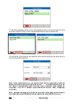
Page 35: ...ss the back arrow to exit and complete the pairing Note If the required device is not shown check that it is powered on with the Bluetooth function active then repeat the search Some Bluetooth devices do not report a recognisable name and may cause confusion when setting up Favourites Turn off or disable unused Bluetooth devices when configuring Favourites Note Seaward and Rigel accessories do not...

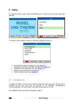
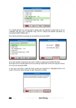
Page 36: ...pter 6 1 Configure the local time and date settings see chapter 6 2 Change the menu language see see chapter 6 3 Restore factory settings see chapter 6 4 View the about screen see chapter 6 5 6 1 Test sequence The Rigel Uni Therm can be set up to perform automatic test sequences These can be created by the user and can be specific to for example manufacturers recommendations The total number of po...

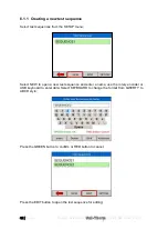
Page 37: ...st sequences from the SETUP menu Select NEW to open a new test sequence and enter a name use the rotary encoder or USB keyboard to enter data Select KEYBOARD to change the format from QWERTY to ABCD style Press the GREEN button to confirm or RED button to cancel Press the EDIT button to open the test sequence for editing ...

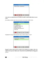
Page 38: ... tests to the test sequence by pressing the ADD button Highlighted the required test using the rotary encoder and press to select Repeat the above steps until the required test sequence is completed Note that additional tests can be inserted in the test sequence by highlighting the position in the sequence and press the ADD button The test will be inserted AFTER the highlighted position ...

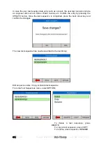
Page 39: ...electing the OPTIONS button Edit individual tests by selecting the required test and press EDIT Once the selected criteria have been set confirm by pressing the UPDATE button User tests can be inserted and used for providing instructions to the test engineer Select the user test and press EDIT In the user test screen select the field you want to edit which is highlighted with a red border Press th...

Page 40: ... Celsius etc Confirm the entry by pressing the UPDATE button Once the test sequence is completed press the back arrow key and confirm the changes The new test sequence has now been added to the test library Edit sequence name Copy or Delete test sequence From the Test Sequences menu select OPTION To delete a test sequence press DELETE To copy a test sequence press COPY To rename a test sequence RE...

Page 41: ... DD to change between MM DD and DD MM format Use the rotary encoder to navigate push to activate field and change values using the rotary encoder Press SAVE to confirm 6 3 Language To change the language select the language option in the setup menu see below Use the rotary encoder to navigate push to select the language Press the back button F1 to confirm or return to previous menu The list of lan...

Page 42: ...r is given an option to select which part of the memory is being restored to the factory default To restore factory default select the factory restore option in the setup menu see below An overview of the memory usage is provided Press NEXT to select which part of the memory to restore to factory default Use the rotary encoder to select which part of the memory is being affected Individual assets ...

Page 43: ... a l V 1 0 6 5 About The about screen shows the firmware versions and serial number of your device Ensure you have this information available when contacting Rigel Medical for Technical Support or Service See chapter 7 4 for more information on Service and Calibration ...

Page 44: ...its reliability If the Rigel Uni Therm is subject to condensation allow the Analyser to completely dry before use Always check the Rigel Uni Therm and all test leads for signs of damage and wear before use Do not open the Rigel Uni Therm under any circumstances Keep the instrument clean and dry Avoid testing in conditions of high electrostatic or electromagnetic fields Maintenance should only be p...

Page 45: ...nd Tel 44 0 191 587 8739 Fax 44 0 191 586 0227 sales rigelmedical com service calibrationhouse com www calibrationhouse com www rigelmedical com Prior to returning your unit for service please contact our service department to obtain a Returns Number By obtaining a Returns Number your service request can be booked in advance thus reducing the down time of your equipment When asking for a Returns N...

Page 46: ...idth with load bank 30 Hz to 2 5 MHz 3 dB Interference Frequency Filter 100 Hz high pass filter Isolation earth to measurement device 10kV Measurement delay adjustment Foot switch delay selectable between 200 5000ms 10ms resolution Variable Load 0 5115Ω steps 5Ω Load Resistor Type Ceramic Resistors Non inductive Accuracy 1 0 5 0 0 Ω of set load Power rating See load power graph Duty cycle Up to 10...

Page 47: ...mm black Remote foot switch control CUT 2 x 4 mm yellow Single relay contact Remote foot switch control COAG 2 x 4 mm blue Single relay contact USB B port USB A port PC interface Key board Data Storage and Recall Memory 4Mb Output CSV format sss test sequences results reference power graphs 8 2 General Specification Dimensions 370 X 300 X 204mm Weight 11 Kg Operating Temperature 10 C to 40 C Stora...

Page 48: ... Load mode Current Limit 8 A rms No power rating user supplied Load Max Watts at 15sec On 15sec Off 50 duty cycle 5 5115 ohms 0 200 400 600 800 1000 1200 1400 1600 1 10 100 1000 10000 Ohms Watts Max Watt at 60sec On 15sec Off duty cycle 5 100 ohms 0 100 200 300 400 500 600 700 800 900 5 15 25 35 45 55 65 75 85 95 Ohms Watts ...

Page 49: ...ax Amps at 15sec On 15sec Off 50 duty cycle 5 5115 ohms 0 00 1 00 2 00 3 00 4 00 5 00 6 00 7 00 1 10 100 1000 10000 Ohms Amps rms Max Amps at 60sec On 15sec Off duty cycle 5 100 ohms 0 00 0 50 1 00 1 50 2 00 2 50 3 00 3 50 4 00 4 50 5 00 5 15 25 35 45 55 65 75 85 95 Ohms Amps rms ...

Page 50: ...chnical enquiries Tel 44 0 191 587 8701 Email support rigelmedical com Rigel Medical 15 18 Bracken Hill South West Industrial Estate Peterlee County Durham SR8 2SW United Kingdom CalibrationHouse Contact details CalibrationHouse Address details Service Calibration and Repair Tel 44 0 191 587 8739 Fax 44 0 191 518 4666 Email info calibrationhouse com CalibrationHouse 11 Bracken Hill South West Indu...

Page 51: ...OLATED ESU BIPOLAR ELECTRODE CUT MODE SECOND ELECTRODE TEST CODE 1121 IEC 601 2 2 part 1 FIGURE 104 MEASUREMENT OF H F LEAKAGE CURRENT FROM A BIPOLAR ELECTRODE EARTH ISOLATED ESU BIPOLAR ELECTRODE COAG MODE FIRST ELECTRODE TEST CODE 1122 IEC 601 2 2 part 1 FIGURE 104 MEASUREMENT OF H F LEAKAGE CURRENT FROM A BIPOLAR ELECTRODE EARTH ISOLATED ESU BIPOLAR ELECTRODE COAG MODE SECOND ELECTRODE TEST COD...

Page 52: ...QUENCY EARTH ISOLATED ESU MONO POLAR ELECTRODE COAG MODE ACTIVE ELECTRODE TEST CODE 1222 IEC 601 2 2 part 1 FIGURE 103 MEASUREMENT OF H F LEAKAGE CURRENT WITH NEUTRAL ELECTRODE ISOLATED FROM EARTH AT HIGH FREQUENCY EARTH ISOLATED ESU MONO POLAR ELECTRODE COAG MODE NEUTRAL ELECTRODE TEST CODE 2111 IEC 601 2 2 part 1 FIGURE 104 MEASUREMENT OF H F LEAKAGE CURRENT FROM A BIPOLAR ELECTRODE EARTH REFERE...

Page 53: ... 1 FIGURE 102 MEASUREMENT OF H F LEAKAGE CURRENT WITH NEUTRAL ELECTRODE REFERENCED TO EARTH AND LOAD FROM ACTIVE ELECTRODE TO EARTH EARTH REFERENCED ESU MONO POLAR ELECTRODE CUT MODE ACTIVE ELECTRODE TEST CODE 2212 IEC 601 2 2 part 1 FIGURE 101 MEASUREMENT OF H F LEAKAGE CURRENT WITH NEUTRAL ELECTRODE REFERENCED TO EARTH AND LOAD BETWEEN ELECTRODES EARTH REFERENCED ESU MONO POLAR ELECTRODE CUT MOD...

Page 54: ... m u s e r M a n u a l V 1 0 TEST CODE 2222 IEC 601 2 2 part 1 FIGURE 101 MEASUREMENT OF H F LEAKAGE CURRENT WITH NEUTRAL ELECTRODE REFERENCED TO EARTH AND LOAD BETWEEN ELECTRODES EARTH REFERENCED ESU MONO POLAR ELECTRODE COAG MODE NEUTRAL ELECTRODE ...

Page 55: ... 601 2 2 part 1 FIGURE 106 MEASUREMENT OF OUTPUT POWER BI POLAR OUTPUT USER SET LOAD RESISTANCE BI POLAR ELECTRODE COAG MODE BOTH ELECTRODES TEST CODE 0210 IEC 601 2 2 part 1 FIGURE 105 MEASUREMENT OF OUTPUT POWER MONO POLAR OUTPUT USER SET LOAD RESISTANCE MONO POLAR ELECTRODE CUT MODE ACTIVE AND NEUTRAL ELECTRODE TEST CODE 0220 IEC 601 2 2 part 1 FIGURE 105 MEASUREMENT OF OUTPUT POWER MONO POLAR ...

Page 56: ...Uni Therm 10 is the number of points on the graph this can be changed but the lines of data must reflect this number Column A is the X axis and represents the Load Ω Column B is the Y axis and represents the Power W In this example line 3 is a plot of 290W at 175Ω Once you have completed plotting the points in the CSV file select File Save As and save the file with a recognisable name and as file ...

Page 57: ...52 P a g e R i g e l M e d i c a l U n i T h e r m u s e r M a n u a l V 1 0 Select the UPPER and LOWER limit graphs by pressing UPPER and LOWER respectively and select the corresponding graphs ...

Page 58: ...ansfer test sequences BT Favourites Pair PC and barcode scanners Setup Test Sequences View create and edit test sequences Time Date Change time and date settings Language Change language settings Factory Restore Restore instrument to factory default About View firmware revision and serial number REM test Manual testing of the REM function HF Leakage Manual testing of the HF leakage Power Manual te...

Reviews: