20035745
24
GB
Start-up, calibration and operation of the burner
7.4
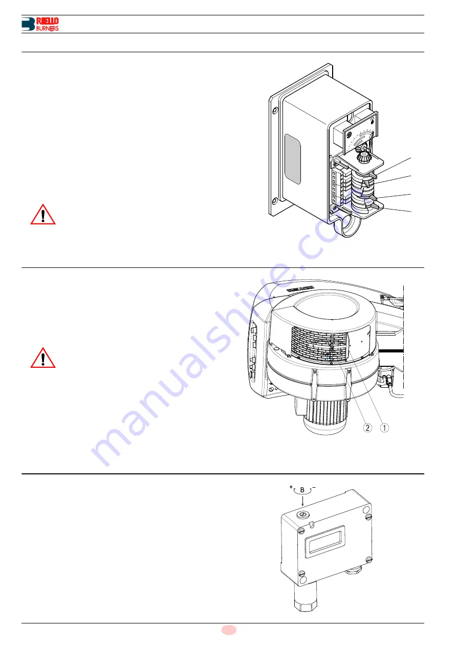
Servomotor
The servomotor (Fig. 22), by means of connection mechanisms,
simultaneously regulates air pressure and delivery and the flow
of fuel in use. It features adjustable cams that operate as many
switches.
Cam 1:
blue
limits servomotor travel to 0° position. With the burner
off, the air damper is fully closed.
Cam 2:
orange
adjusts the position of the air damper to 1
st
stage or
pre-purging (factory set to 22° position).
Cam 3:
red
adjusts air damper travel or 2
nd
stage operation with-
out exceeding 90° (factory set to 60° position).
Cam 4:
black
determines how early 2
nd
stage valve is switched on.
7.5
Air adjustment for maximum output
Set the servomotor to maximum opening (near 90°) so that the air
butterfly valves are fully open.
Loosen screw 2)(Fig. 23) under the burner’s intake and close
grille 1) progressively until you achieve the required output.
The only time reducing intake to a partial setting is not necessary
is when the burner is working at the top of the operating range
given on page 11.
7.6
Low-limit oil pressure switch
The low-limit oil pressure switch inhibits burner ignition at a pres-
sure below the pump's setting.
See Tab. F to page 17 (it comes with a factory setting of 8 bar).
If pressure is below the pump setting, the start-up cycle begins as
usual but, when the burner is to ignite, it locks out owing to the oil
pressure switch tripping.
Adjustment is made using screw B)(Fig. 24).
WARNING
Under no circumstances should the blue cam be
moved to the left, beyond the air damper closing
position.
Under no circumstances should the red cam be
moved to the right beyond 90°.
Fig. 22
4
3
2
1
D3326
WARNING
We recommend you achieve the maximum output
required manually, and adjust intake to the partial
setting and adjust the combustion head before
completing servomotor setting.
Fig. 23
D3094
Fig. 24
D3393


